Robot gripper fingers are the only part of the tool that touches the workpiece, so they decide whether a cell grips the same way on the first cycle and on the ten-thousandth — and they are usually designed last, after the gripper body has already been ordered. The body supplies motion and force; the robot gripper fingers decide how that force reaches the part.
Most selection conversations stop at the body, and the fingers become an integration detail — by which point the body size and mounting pattern are fixed. Working through robot gripper fingers from the part backwards avoids that, in the order the decisions usually matter: the part, the contact, the material, stiffness, mounting, and replacement.
On this page
Why robot gripper fingers fail before the gripper does
A gripper body is a manufactured mechanism with a datasheet and a warranty. A finger is often a piece of bar stock sketched on a print over a weekend. That difference in attention is why most handling problems trace back to the tool-to-part interface rather than the tool. Read the symptom backwards: most complaints described as gripper problems are finger problems once the evidence is unpacked.
| Symptom | What it usually means | Blamed by default |
|---|---|---|
| Part slips under acceleration | Contact friction or surface, not force | Gripper force rating |
| Part shifts between picks | Finger deflection or uneven contact | Robot repeatability |
| Scuffs and dents | Pressure concentrated on a small area | Closing force |
| Placement drifts over a shift | Pad compression set or face wear | Vision or fixture |
| Part off-centre after the pick | Asymmetric fingers; one jaw contacts first | Robot teaching |
| Fine on the sample, poor on production | Fingers shaped around one part only | Incoming material |
None of those rows justifies a stronger gripper. Each is a reason to re-examine how the robot gripper fingers meet the part, which costs a drawing revision rather than a new tool.
What the part tells you before you draw anything
Robot gripper fingers start from five inputs that have nothing to do with grippers. Collect them before anyone opens a catalogue, because each one closes off a class of concept immediately.
- The gripped feature. Not the part outline. A finger that grabs the widest face of a casting may be holding a draft angle; one that grabs a machined flat is holding a surface made deliberately parallel.
- Tolerance across the batch. The nominal dimension is the least useful number on the drawing. The tolerance band, plus supplier variation, is what the robot gripper fingers must span.
- Mass and acceleration. Force at the contact is set by mass, available friction, and the worst acceleration in the move. A heavy, smooth part needs geometry that resists sliding, not more pressure.
- Surface condition and the cost of a mark. A polished cosmetic face and a sand-blasted bracket pull the contact in different directions, usually resolved with pad material rather than finger shape.
- Presentation accuracy. A fixtured part allows tight, simple jaws; a bin-picked part asks the robot gripper fingers to absorb a position nobody guarantees.
Contact profile options and what each one does to the surface
Contact profile is the shape of the finger where the robot gripper fingers meet the part, and it affects part quality more than any other decision. Force spreads over area, so the same closing setting gives a very different result whether contact spreads across a face or concentrates on a line.
| Profile | How load is carried | Fits when | Disappoints when |
|---|---|---|---|
| Flat pad | Broad area, pressure spread | Two parallel machined faces exist | Faces are tapered or not parallel |
| Vee jaw | Two lines, self-centring | Round parts of varying diameter | Soft parts; pressure concentrates |
| Spherical contact | Small area, high pressure | Location matters more than finish | Thin parts; leaves witness marks |
| Serrated face | Mechanically interlocks | Heavy, oily, or scaled parts | Finished surfaces; debris packs the teeth |
| Conformable pad | Deforms to follow the shape | Curved, irregular, delicate parts | Compresses, so position drifts |
| Swivelling tip | Rotates to match an angle | Cast faces, varying arrival angles | Extra clearance and movement |
The pattern is a trade: the more the contact self-aligns or spreads load, the more it costs surface quality or introduces movement. When robot gripper fingers meet a delicate part where position also matters, the usual answer is a large conformable contact with a light closing force rather than a smaller hard contact pressed harder.
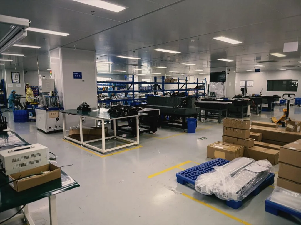
Custom gripper jaws: when a standard finger cannot reach the feature
Standard robot gripper fingers are rectangular blanks with a bolt pattern. They suit parts gripped on an accessible outside face, and they stop working when the feature sits inside a recess, behind a flange, or below a lip. The question is then no longer how wide the fingers open but where along their length contact lands.
- Stepped fingers. A shoulder passes a flange and contacts a smaller feature, and the step must clear the flange over the full travel.
- Offset fingers. Moving contact off the mounting axis buys clearance from a blocked approach, at the cost of a larger bending moment.
- Blade profiles for thin walls. Thin parts need contact near a supported edge, because a long unsupported span bows under clamping.
- Floating pads. When the two faces are not parallel, a small floating element lets both load, at the cost of clearance and accuracy.
The most accurate answer for one high-volume part is custom gripper jaws machined around it, and the least forgiving for anything else. Add them only when the part will not change for the life of the cell.
Gripper finger material: matching the finger to the part
Gripper finger material is chosen on three grounds, in this order: what it does to the part surface, how it behaves under repeated load, and how easily it machines into the required shape. Stiffness and wear resistance follow from those.
| Material | Strength here | Struggles with |
|---|---|---|
| Aluminium | Light, quick to machine | Wears fast; needs a pad or insert |
| Alloy steel | Stiff for a given section | Heavy at the wrist; marks bare parts |
| Stainless steel | Washdown and coolant | Harder to machine; still marks parts |
| POM or acetal | Machines cleanly, low friction | Creeps under load; not for hot parts |
| Polyurethane pad | High friction, protects finish | Compresses, so grip position changes |
| PEEK or similar | Holds shape hot; insulating | Cost, where a cheaper pad would do |
In practice most robot gripper fingers are a metal structure with a replaceable contact pad, so the material question splits in two: what carries the load and what touches the part. Making that split deliberate keeps the wear part cheap to change, and it separates structural deflection — a design problem — from pad wear, a maintenance item.
Stiffness and reach: the cantilever behind the grip
Each finger is a cantilever with the contact force acting at its tip, so deflection grows roughly with the cube of the overhang and falls with the stiffness of the section. Lengthening robot gripper fingers to reach a feature is one of the most expensive geometric changes available, even though it costs nothing on a drawing.
Deflection matters three ways: it consumes commanded closing travel, it makes grip position load-dependent, and it lets the contact faces rotate relative to each other, turning a flat contact into an edge contact and then into a mark.
| Change to the finger | Effect on stiffness | Consequence |
|---|---|---|
| Longer, same section | Falls steeply with overhang | Contact position becomes load-dependent |
| Deeper section | Rises strongly with depth | Cheapest stiffness if the envelope allows |
| Wider section | Rises in proportion to width | Works, but adds mass for less gain |
| Contact outboard of the bolts | Adds a lever arm on the joint | Bolt preload becomes part of grip quality |
| Bolt-on tip | Adds joint clearance | Repeatability drops after every remount |
The habit that follows is to keep the load path short and the section deep. A short, deep finger with a bolted-on tip usually outperforms long slim robot gripper fingers made in one piece.
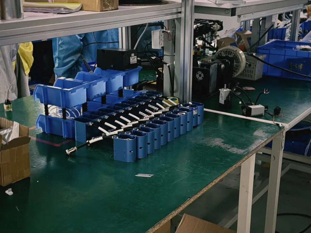
Mounting interfaces and what a finger change really involves
The connection between robot gripper fingers and the body looks trivial and is where repeatability quietly disappears. Every interface adds compliance and a tolerance stack, and remounting a finger is not repeatable unless the interface is designed to be.
- Bolt pattern. Screws should load the joint in tension and be reachable with a torque wrench. Recessed screws that need the finger removed before they can be tightened are a maintenance trap.
- Location features. Dowel pins or a machined register make a remount land in the same place. Without one, position is defined by bolt hole clearance.
- Repeated removal. Robot gripper fingers come off for cleaning, pad replacement, and changeover, and each cycle is a chance of a different clamp position.
Ask what happens if the robot gripper fingers are removed and refitted by someone who did not design them. If the part runs differently until it is retaught, the interface needs a register.
Designing robot gripper fingers for a part family
Most production cells run a family, not a single part. Robot gripper fingers for a family should be built around a common base that stays on the gripper, with contact tips that change per part or per size group, so the registered interface is untouched during a changeover. A whole finger set has to be re-registered and often retaught; a tip swap does not.
The trap is covering the family with one set of robot gripper fingers. Such a design must reach the smallest part and clear the largest, and the compromise usually shows up as contact at an awkward point along the finger. If the size range is wide, or the gripped features differ in kind, swappable tips grip better; programmable force and position handle the parts in between, but cannot compensate for a contact face in the wrong place.
Wear parts and replacement planning
Robot gripper fingers are consumables in everything but name. Contact faces wear, pads compress, joints loosen, and a part gripped perfectly at commissioning slowly stops being gripped the same way.
| Wear location | Driven by | What to check |
|---|---|---|
| Contact pad surface | Sliding on every pick; abrasive parts | Pad thickness, texture, marks on the part |
| Pad fixing or bond | Shear from each pick and place | Lifted edges, debris under the pad |
| Tip edge | Contact with fixtures and chutes | Burrs that move the contact line |
| Mounting joint | Load reversal and remounting | Bolt torque, witness marks |
| Finger body | Overload from collisions | Cracks at section changes, bend |
Three practices keep this under control. Make the pad a separate cheap part so wear costs minutes rather than a finger set. Keep spare tips on the shelf with the part number on the cell documentation. And define a check a technician can do without instruments: a look plus a part-position check at the first maintenance window catches most compressed pads and moved joints.
Debris on the pad is the most common cause of a slow decline in grip quality, because air lines, coolant and part dust all end up on the contact face.
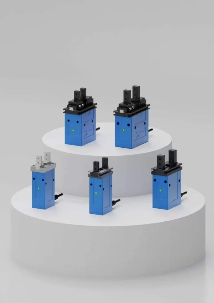
Worked example: finger notes for one machined housing
The following is an illustrative derivation, not a specification for any model. Suppose a cell loads machined aluminium housings, 38 to 42 mm across the gripped flats, weighing a few hundred grams, presented with about a millimetre of scatter, and the visible face must stay mark-free.
| Design step | Illustrative choice | Reason |
|---|---|---|
| Gripped feature | The two machined side flats | Parallel, toleranced, hidden after assembly |
| Contact profile | Flat pad across the face width | Spreads pressure; avoids marks a point would leave |
| Pad material | Replaceable polymer pad on metal | Protects finish and becomes the wear part |
| Finger body | Short and deep, no extension | Keeps deflection low |
| Mounting | Registered on a dowel | Refit without recalibrating |
| Family handling | Common base, two tip variants | Covers the spread without touching the interface |
| Verification | Tolerance extremes plus feeder scatter | Tests the range, not the nominal part |
Two things generalise. The contact decision was made on surface and location grounds before any force figure was discussed, and family handling was designed into the interface so a size change is a tip swap. Where force and closing position sit alongside the design of robot gripper fingers is covered under gripping force and electric gripper stroke.
A checklist before the fingers go to the machine shop
Every item below concerns robot gripper fingers and can be answered from the part drawing, the cell layout, and the process sheet.
- Is the gripped feature named and agreed? Not the outline, and not the face that merely happens to be cleanest.
- Does the contact match the process? A mark-free cosmetic surface and a serrated face are not compatible.
- Was the tolerance band used, not the nominal? Robot gripper fingers built around a nominal dimension fail on the extremes of the same batch.
- Are the fingers as short as reach allows? Every extra millimetre of overhang is paid for in deflection.
- Is the pad a separate listed part? If not, wear becomes a finger replacement.
- Is there a register for remounting? Bolt hole clearance is not a location feature.
- Does a spare set exist? The second set is cheapest bought with the first.
Review robot gripper fingers whenever the part changes, even slightly: a revised chamfer, a new supplier, or a few tenths of movement in the gripped dimension can invalidate a contact concept that was comfortable before. On a two-finger tool the choices interlock with the jaw arrangement, compared in parallel gripper vs 3-jaw gripper; the role of the fingers within a complete end-of-arm tool is set out in what is a robot gripper.
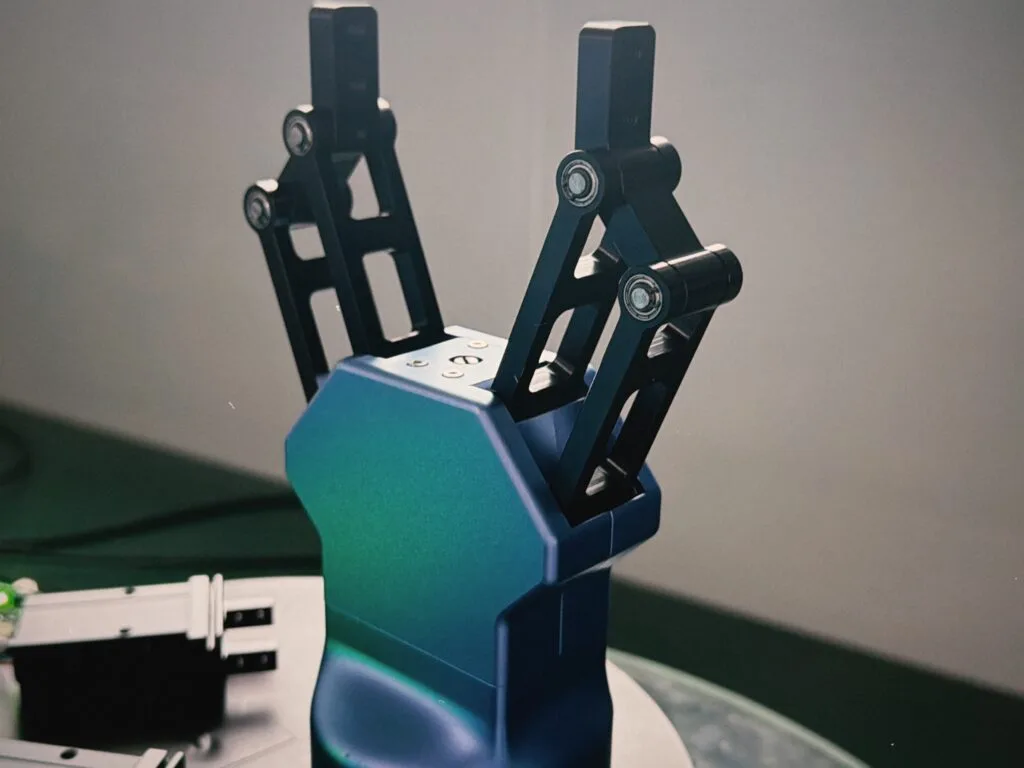
When comparing EPGS-6-10 and EPGS-12P-15, use their published stroke and mass references and request current drawings. Check the complete tool and finger load against the robot limits. The finger contact geometry must suit the actual part.
Frequently asked questions
Should robot gripper fingers be designed before or after the gripper is chosen?
In parallel, with the contact concept settled first. The part, the gripped feature, and the surface requirement define what the finger must do, and those answers constrain the mounting interface and closing behaviour needed. Choosing the body first usually means accepting an envelope the right finger will not fit.
How do I stop robot gripper fingers from marking the part?
Reduce contact pressure before adding anything else. A larger contact area, a conformable pad, and a lighter closing force solve most marking problems. Serrated or hardened faces raise local pressure and are the usual cause of marks.
Can one set of robot gripper fingers handle a whole part family?
Only when the parts are close in size and share a gripped feature. Once the family spans a wide range, or the gripped geometry changes, a single set forces a compromise that appears as poor contact at one end of the range. A common base with swappable tips usually handles a family better.
Why do robot gripper fingers seem to lose position over time?
Check the pads and the mounting joint before suspecting the body. Compressible pads take a set, wear faces change shape, and bolted joints settle. All three shift the contact position gradually, which is why the pad and joint belong in the maintenance routine.
Does a stiffer finger always give a better grip?
A stiffer finger gives a more predictable grip, which is not the same thing. Where the part is delicate or the faces are not parallel, controlled compliance can be the better answer because it lets both contacts load without crushing the part. Specify the stiffness of robot gripper fingers against the accuracy the process needs.
Need help selecting a gripper?
Send your part drawing, robot model, required stroke, clamping force, country, and quantity for a practical model shortlist.