Electric gripper stroke is the distance the fingers travel between the fully open and fully closed positions, and it should be written as a range that covers every part the cell will run, not as a single number copied from the widest component on the drawing. Stroke is easy to compare between models and difficult to specify correctly, which is why it is one of the most common sources of a gripper that almost works.
Most teams start from the part width and pick the gripper with the nearest opening. That approach ignores the fingers, the placement error of the feeder, and the difference between one part and a family of parts. The result is usually a gripper that holds the nominal part well and struggles with everything else on the same line. Writing the electric gripper stroke requirement from the part family rather than from the catalogue is what avoids that outcome.
On this page
What stroke and jaw opening each describe
Supplier datasheets do not use these terms consistently, so the first step is to establish which quantity each number on a page actually refers to. Comparing two models without that check compares nothing, and an electric gripper stroke figure copied from the wrong row will look entirely reasonable until the fingers meet the part.
| Term as written | What it describes | Where it usually appears |
|---|---|---|
| Stroke | Total distance the fingers cover between the open and closed limits, across both fingers | Headline specification line |
| Per-jaw travel | Distance a single finger moves, typically half the total on a symmetric gripper | Motion or mechanism section |
| Jaw opening | Clear distance between the fingers at a defined position, often fully open | Outline drawing dimension |
| Mounting pitch | Distance between the faces where the fingers bolt on, before any finger is fitted | Outline drawing |
On a symmetric two-finger gripper, per-jaw travel and total stroke differ by a factor of two. Mixing them up produces a specification that looks reasonable on paper and fails on the bench, because the opening that matters is the one measured where the part actually sits, between the finger contact faces. An electric gripper stroke quoted as a single headline number rarely says which of these four quantities it represents.
Where the motion axis sits changes the usable range
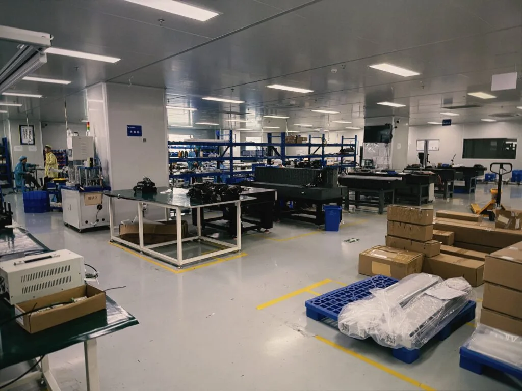
A parallel gripper that opens symmetrically moves each finger half the total travel. That single fact drives two decisions.
- Centering. The part centerline follows the tool axis only while both fingers move equally. On a self-centering mechanism the gripper positions the part, which is an advantage when the feeder is imprecise.
- Space budget. If the cell permits the fingers to open on one side only, a symmetric gripper spends half its travel on space it cannot use.
Some applications need a fixed jaw and a single moving jaw, for example when one face of the part must stay registered against a hard stop. That is a legitimate mechanical choice, but it changes how the usable opening should be described, and it is worth stating explicitly when the electric gripper stroke requirement is passed to a supplier.
Why the part sets the requirement, not the gripper
The productive direction is to build the requirement from the work, then match a model to it. Five inputs drive the number.
| Input | How it changes the stroke requirement |
|---|---|
| Widest and narrowest part | The fingers must clear the largest component and still close onto the smallest |
| Batch tolerance | Widens the range even when the nominal dimension never changes |
| Finger thickness | Consumes opening, because fingers occupy the space between the mounting faces |
| Approach clearance | The gripper often needs to open wider than the part to get around it without touching |
| Placement error | Feeder and fixture variation means the part is not exactly where the program expects it |
The last two are the most frequently omitted. A gripper that clears the part on a drawing can still strike it on a real feeder, and the extra margin is what absorbs that difference without a program change. Every one of these five inputs belongs in the electric gripper stroke calculation, and each of them adds to the range rather than replacing one of the others.
The finger thickness you subtract from every calculation
Fingers are not free space. Whatever thickness they add between the jaw and the part reduces the usable opening, so the quantity the gripper must cover is the part width plus the finger thickness on each side.
This is why two cells that look identical can need different grippers. Thick steel fingers for a rough casting and thin polymer pads for a polished cover occupy very different amounts of the same opening. Settle the finger concept early, because it feeds straight back into the electric gripper stroke number. The wider selection sequence, including how stroke sits alongside force and robot compatibility, is set out in how to choose an electric gripper for a robot arm.
Sizing for the whole family, not the nominal part
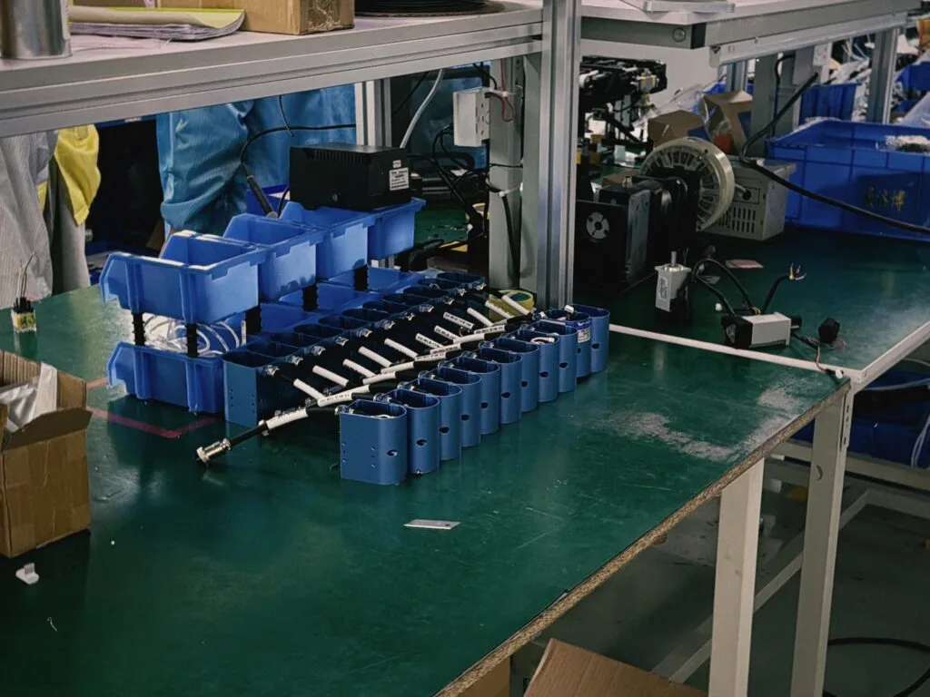
A production cell rarely runs a single part. When the line handles a family, the electric gripper stroke range must cover the extremes, and then that range has to be checked against how accurately the gripper can close at the narrow end.
Two limits pull against each other:
- The open limit. Set by the widest part plus finger thickness plus approach clearance. Miss this and the gripper collides on the pick.
- The closed limit. Set by the narrowest part. Miss this and the fingers never reach the surface, or they reach it with so little remaining travel that the closing force is delivered at an awkward point in the mechanism.
For EPG2-26-15 and EPG4-10-50, compare the published stroke reference and request current outline and fingertip-interface drawings. Check both the smallest and largest parts in the proposed family.
Why a longer stroke is not automatically better
Extra travel always costs something. It is rarely free, and it is worth knowing the price before ordering a wider electric gripper stroke “for flexibility”.
| Consequence of more travel | What it costs the cell |
|---|---|
| Longer fingers are usually needed to use it | Greater overhang, so fingers deflect more under load |
| More mechanism movement per cycle | Closing time rises on the same drive |
| Larger body envelope | Wrist weight grows and payload margin shrinks |
| Resolution spread over a longer distance | The same feedback resolution covers a coarser per-count step |
None of these are arguments against a long electric gripper stroke where the parts genuinely need it. They are arguments against buying one speculatively, because a wider gripper can make an otherwise comfortable payload budget uncomfortable, and it can slow a cycle that was already tight.
Reaching into a recess: where stroke stops helping
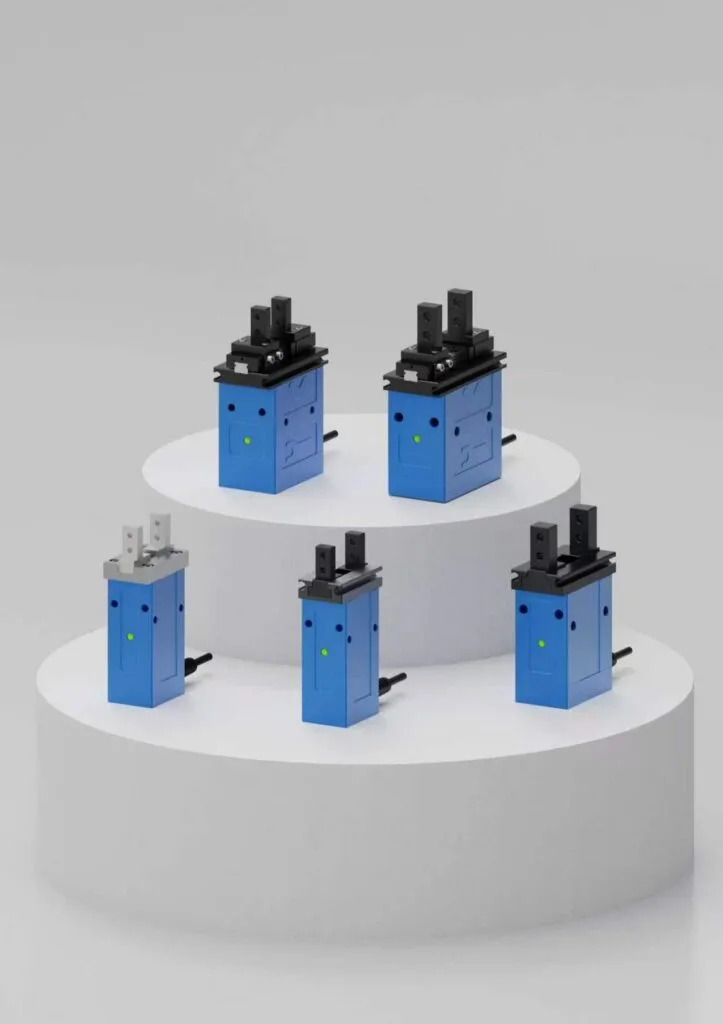
Parts with an internal lip, a bore, a groove, or a flange the fingers must pass before they grip are a different problem from wide parts. Here the issue is not how far the fingers open but where the contact faces are along the finger length.
Opening further does not help a finger that is too short to reach the gripping feature, and lengthening the finger to reach it reintroduces the deflection problem. The practical answers are usually a stepped or offset finger profile, a different contact position on the part, or a change in part presentation so the accessible face becomes the gripped face. Deciding this at the drawing stage is far cheaper than discovering it after the fingers are machined, and it is one case where a larger electric gripper stroke cannot compensate for the wrong finger geometry.
Worked reasoning for one part family
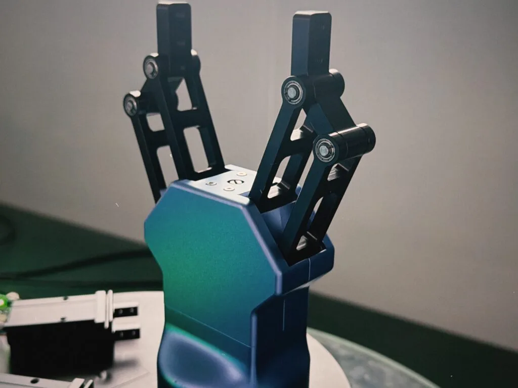
The following is an illustrative derivation, not a specification for any model. Suppose a cell loads machined housings across a family that ranges from 39 mm to 41 mm wide, presented by a feeder with about a millimetre of positional scatter, and the finger concept adds 5 mm per side.
| Step | Illustrative value | Reasoning |
|---|---|---|
| Narrowest part | 39 mm | Sets the closed limit the fingers must reach |
| Widest part | 41 mm | Sets the starting point for the open limit |
| Approach clearance | 2 mm per side | Absorbs feeder scatter so the fingers do not strike the part |
| Required gap between contact faces when open | 45 mm | 41 mm part plus clearance on both sides |
| Finger thickness allowance | 10 mm total | 5 mm per finger, subtracted from the usable opening |
| Indicative opening the mechanism must cover | Roughly 55 mm open, closing to about 39 mm | Leaves roughly 16 mm of travel, plus whatever squeeze margin the process needs |
The value of this exercise is not the arithmetic. It is that the result is a range with a stated reason for each term, so a supplier can respond to the reasoning instead of guessing which margin to shave. The same discipline applies to the force side of the requirement, which is worked through alongside gripping force.
How to state an electric gripper stroke requirement
A requirement that a supplier can answer without a follow-up call has four parts: the range, the reason for each end of it, the finger concept, and the motion the cell can accommodate. Writing those four items down takes a few minutes and removes most of the ambiguity that otherwise comes back as a quotation for the wrong body size.
| Item to state | What to write | Why it matters |
|---|---|---|
| Required range | The narrowest and widest opening the fingers must reach, measured between contact faces | Fixes both ends of the electric gripper stroke requirement instead of one headline number |
| Basis for each end | Which part and which tolerance sets the narrow limit, which part and which clearance sets the wide limit | Lets the supplier propose a different mechanism rather than a larger body |
| Finger concept | Material, thickness per side, and whether the part is contacted on flats, a bore, or a profile | Finger thickness is subtracted from the opening, so it changes the range |
| Motion available | Whether both jaws may move or one must stay fixed against a stop | A fixed jaw halves the usable opening on the same body |
It also helps to say what the cell will do with the part after gripping. A requirement that carries only the electric gripper stroke figure invites a quotation matched to that figure alone; a requirement that carries the process invites a selection proposal, which is usually the more useful reply.
Where the range is genuinely uncertain, state the uncertainty rather than inflating the number. A supplier who knows the scatter is unmeasured can suggest how to measure it. A supplier who is handed an inflated electric gripper stroke requirement has no way to tell that it is a guess, and will size the body accordingly.
Checking electric gripper stroke at commissioning
An electric gripper stroke requirement is only verified when the cell runs the real parts. Four checks settle it quickly, and each one maps back to a term in the calculation rather than to the datasheet.
- Fully open clearance. Command the open position with the widest part in place and confirm the fingers do not touch on approach. If they do, the clearance term was too small rather than the electric gripper stroke being too short.
- Fully closed contact. Command the closed position on the narrowest part and confirm both fingers make contact before the mechanism reaches its limit. Contact at the limit means there is no travel left to develop force.
- Repeatability at the narrow end. Run a batch and check whether the closing position drifts as the mechanism warms up. A range that just covers the smallest part has no room to absorb that drift.
- Finger deflection under load. Watch the contact faces while the part is lifted. Fingers long enough to use a generous open position will bend, and the resulting opening change belongs in the next revision of the requirement.
Any of these checks can send the specification back for revision, and that is the point of running them early. Adjusting an electric gripper stroke requirement after a trial batch is cheap; discovering the same problem after the cell is in production is not.
Common specification mistakes
- Sizing from a single nominal part. The range across the family is what the cell has to survive, not the drawing’s typical value.
- Quoting per-jaw travel as total stroke. A factor-of-two error that only shows up when the gripper cannot clear the part.
- Forgetting finger thickness. The fingers occupy opening, and thick fingers consume a surprising amount of it.
- Leaving out approach clearance. Real feeders place parts approximately, not exactly.
- Buying stroke as insurance. Unused travel is still paid for in weight, envelope, and closing time.
- Deciding the finger design last. Finger concept and the electric gripper stroke requirement are the same calculation.
Frequently asked questions
Is stroke the same as jaw opening?
No. The electric gripper stroke is the distance travelled between the open and closed limits. Jaw opening is the clear distance between the fingers at one defined position. A datasheet may quote either, and sometimes quotes the mounting pitch instead, so confirm which measurement is being given before comparing two models.
Should I always choose the largest available stroke?
Rarely. A larger electric gripper stroke usually means a larger body, longer fingers for the same reach, and a longer closing motion. Choose the smallest range that covers the whole part family with a sensible margin, and treat spare travel as a cost rather than as insurance.
How much extra opening should I allow for part variation?
Enough to cover the widest part in the family plus the finger thickness plus the positioning error of the presentation device. If the scatter of the feeder is unknown, measure it before specifying, because it is often the largest single term in the electric gripper stroke calculation.
Can a gripper hold two very different part sizes without changing fingers?
Sometimes, if the range spans both and the fingers can contact both shapes properly. The difficulty is usually not the travel but the contact geometry, because fingers shaped for a narrow part may barely touch a much wider one. Programmable stroke helps with positioning, not with contact shape.
Does more stroke reduce gripping accuracy?
It can, because the same feedback resolution is spread across a longer travel and the fingers needed to use that travel are longer and less stiff. Whether it matters in practice depends on what the process does with the part after gripping, which is why the electric gripper stroke requirement should come from the process rather than from the gripper catalogue.
Need help selecting a gripper?
Send your part drawing, robot model, required stroke, clamping force, country, and quantity for a practical model shortlist.
Compare stroke on published models
Start with EPGS-6-10 for compact travel, EPG2-100-50 for a wider opening, and EPGL-200-1200 for long stroke. Check each model page for current values.