On this page
Choosing an electric gripper starts with the part, not the catalog. The part’s shape, weight, surface, and the way it has to be presented decide the stroke, the force, and the finger design. The gripper is selected last, from those numbers.
Most wrong selections trace back to the same shortcut: picking a gripper by jaw opening, then discovering later that the force, the finger shape, or the communication does not fit the cell.
Step 1 — Describe the part and the task
Before any model is compared, collect:
- Part drawing or a clear photo with a scale
- Part weight, and whether it varies between batches
- Surface condition — machined, cast, painted, coated, oily, hot
- Where the gripper is allowed to touch, and where it is not
- How accurately the part has to be placed, not just held
- Cycle time target for the whole move, not only the grip
The tolerance of the incoming part matters here. If part-to-part variation is wide, the gripper has to accommodate it, either through stroke range or through a compliant contact.
Step 2 — Work out the stroke
Stroke is the distance the fingers travel, and it has to cover more than the part dimension.
| Requirement | What it means |
|---|---|
| Open width | Must exceed the widest part plus finger thickness plus clearance for loading |
| Closed width | Must be narrow enough to grip the smallest part variation |
| Loading clearance | Space needed to approach and withdraw without touching the fixture |
| Insertion depth | Some processes need the fingers to reach into a recess, which changes finger design rather than stroke |
A useful rule is to specify stroke from the smallest and largest part in the same station, then add clearance for approach. If the range is too wide for one gripper, that is a sign the station needs two tools rather than a compromise.
Step 3 — Work out the clamping force
Force is where most errors happen, in both directions. Too little force drops the part; too much deforms it.
The starting point is the load the grip has to resist:
- Static weight — the part’s own mass under gravity
- Dynamic load — acceleration and deceleration of the robot, which can exceed the static weight several times over
- Process loads — insertion force, torque during rotation, or reaction from a downstream operation
- Surface friction — a smooth or oily surface needs more normal force for the same holding capability
In practice, the required clamping force is estimated from the part mass, the acceleration it will see, the friction at the contact, and the number of contact faces, then a safety margin is applied on top. The safety factor exists because friction varies with surface condition and with wear on the contact pads.
Two cautions:
- Do not select at the calculated minimum. With no margin, the first change in surface finish or pad wear causes a drop.
- Check the part’s limit, not only the gripper’s. If the required force approaches what the part can take, the answer is usually a better contact design rather than more force.
Step 4 — Check compatibility with the robot
| Item | Why it matters |
|---|---|
| Payload | Gripper weight, fingers, cable, and part all count against the arm’s rated payload |
| Moment and torque limits | A gripper offset far from the flange loads the wrist more than its weight alone suggests |
| Mounting interface | Mechanical interface must match the robot flange pattern |
| Wrist clearance | Gripper body and fingers must not collide with the arm during the full path |
| Cable routing | The cable has to survive the full range of wrist rotation without binding |
On a cobot, payload discipline matters more than on an industrial arm. Every kilogram of tool comes directly off the weight the cobot can carry, so a heavy gripper can quietly reduce the part weight the cell can handle.
Step 5 — Decide how it will be controlled
This choice is often made late and causes the most rework. The gripper has to communicate with whatever is running the cell:
- Simple digital I/O — open and close commands with basic status back. Cheapest and easiest to integrate.
- Serial or Modbus connection — position, force, and status data available to the controller.
- Fieldbus — where the cell already runs a network and the gripper should join it as a standard node.
- Integrated drive and control — the controller sits inside the gripper body, reducing cabinet space and wiring.
Confirm this before ordering, not after. A gripper with excellent mechanics and the wrong interface still stops the project.
Step 6 — Check the environment
- Coolant and chips — common in machine tending; drives the required ingress protection and the finger material.
- Dust — found in casting, sanding, and powder handling.
- Washdown — food and pharmaceutical lines often need a higher protection class.
- Temperature — hot parts transfer heat through the fingers into the mechanism.
- Cleanroom — some environments restrict lubricants and require specific materials.
The information that produces a fast, accurate quote
| Input | Typical detail |
|---|---|
| Part | Drawing or photo, material, weight, surface |
| Geometry | Gripping width at open and closed, allowed contact areas |
| Force | Estimated minimum and maximum acceptable |
| Stroke | Smallest and largest part in the station |
| Robot | Brand and model, or at least payload and flange standard |
| Control | I/O, Modbus, fieldbus, or controller type |
| Environment | Coolant, dust, washdown, temperature |
| Commercial | Annual quantity, destination country, timeline |
Common selection mistakes
- Choosing by jaw opening alone. The easiest number to compare is rarely the deciding one.
- Ignoring dynamic load. A grip that holds on the bench can fail at full speed.
- Leaving finger design to the end. The fingers are the actual contact with the part.
- Sizing force with no margin. No allowance for surface variation or pad wear.
- Settling the interface late. Communication mismatch delays the whole integration.
- Forgetting the cable at the wrist. A routing failure looks like a gripper failure but is a design failure.
Frequently asked questions
How much clamping force do I need?
It depends on part mass, the acceleration the robot will apply, the friction at the contact surfaces, and how many faces are gripping. The calculation gives a minimum; a margin is then added for surface variation and wear. If you can supply part weight, acceleration, and surface condition, a supplier can estimate a range for you.
Can I use a gripper that is larger than needed?
Usually yes, with two penalties: extra weight on the wrist, and a larger body that may not fit the workspace. Oversizing force is not harmful if the force is controllable, which is one reason programmable force is useful.
Should stroke be as large as possible?
Not necessarily. A very long stroke often brings a larger, heavier mechanism. Selecting the stroke range the station actually needs usually gives a better result than choosing the widest available.
What is the most common reason a gripper underperforms after installation?
In practice, finger design and cable routing cause more problems than the gripper mechanism itself. Both are usually decided late in the project, when there is little time left to correct them.
Do I need force and position feedback?
Only if the process uses it. Feedback is valuable when parts vary, when force must be verified for quality, or when the controller needs to confirm that a grip actually happened. On a simple transfer it may add cost without benefit.
Need help selecting a gripper?
Send your part drawing, robot model, required stroke, clamping force, country, and quantity for a practical model shortlist.
Image reference
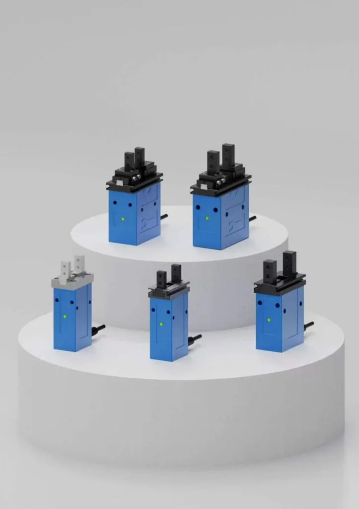
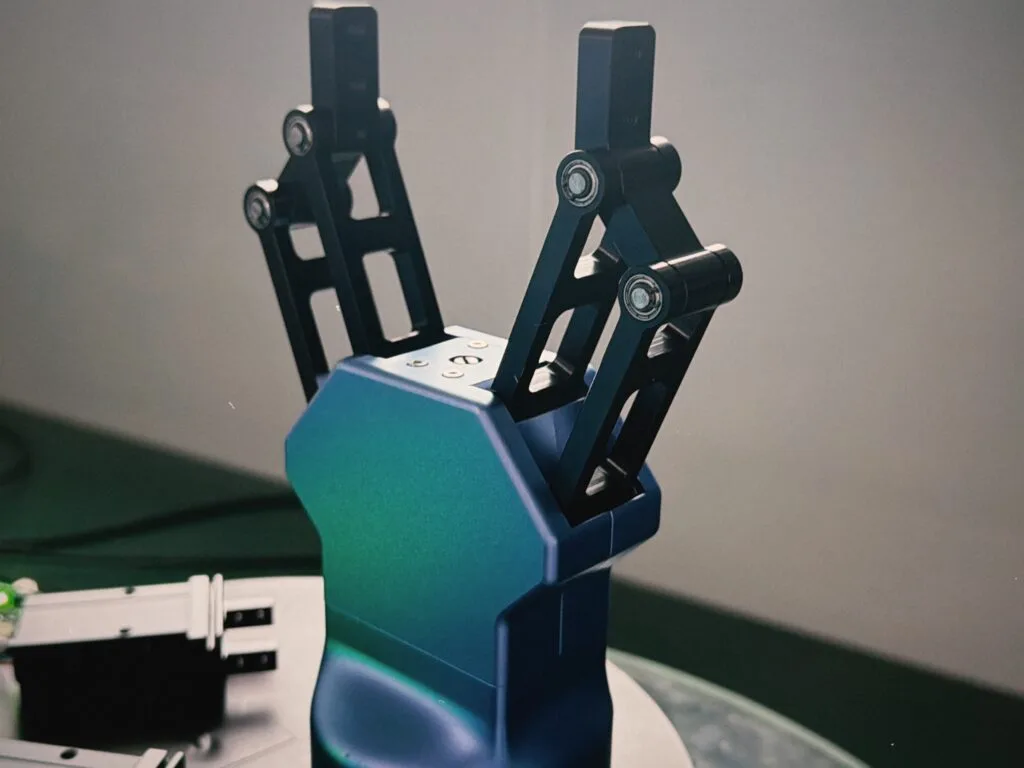
Choose by stroke, load and gripping force
- Stroke: Among models whose travel covers the part and release clearance, choose the closest suitable stroke.
- Load: Keep the part mass below the model’s maximum recommended clamping load.
- Force: Estimate the required contact force for the fingers and motion. Move to another model if any check fails.
For an initial estimate, use F ≈ m × g × S ÷ (μ × n), where m is part mass, g is 9.81 m/s², S is a safety factor, μ is the contact friction coefficient and n is the number of contact faces. Typical starting factors are S = 2 for a static hold, 3 with acceleration and 4 for harsh conditions; friction estimates are 0.5–0.8 for steel against rubber and 0.15–0.2 for dry steel against steel.
Worked check: A 76 mm steel tube weighing about 3 kg fits the stroke of EPG2-100-50, but exceeds its 2 kg maximum recommended clamping load. At S = 3 and two contact faces, the estimate is about 88 N with μ = 0.5 rubber pads or 392 N with μ = 0.15 dry steel contact. Ask us to review the next suitable model, finger design and operating conditions.
The formula and friction/safety factors are general engineering practice, not manufacturer data. Use them for estimation only and confirm with us.
What to send for selection
- Part size range, mass, material, surface and drawing.
- Motion or rotation, acceleration, cycle target and finger arrangement.
- Robot and mounting details, available space and desired I/O, Modbus RTU or EtherCAT control.
Compare the EPGS-6-10, EPG2-100-50 and EPGL-200-1200 pages, then request the current drawing and configuration for the shortlisted model.