The integrated gripper controller question is about what you are willing to move onto the wrist, not about which arrangement is better in general. When drive electronics live inside the gripper body, a cabinet device, its rail space and the cable run between them disappear. You pay in flange mass, heat at the work face, and a service action that swaps a tool rather than a board.
Most projects reach the integrated gripper controller decision late, after stroke and force are fixed. That order causes rework: the arrangement changes wrist weight, cable count and cabinet layout, so it belongs in the same pass as the gripper itself, not in integration week when the cabinet door no longer closes.
On this page
Why the integrated gripper controller question surfaces late
Selection starts from the part. Stroke, jaw opening, gripping force and finger geometry get fixed first because they are visible on the drawing. The controller arrangement sits behind them and has no obvious owner: mechanical owns the tool, controls owns the cabinet, and the integrated gripper controller choice falls between the two.
By then three things are already ordered: the robot and its payload rating, the cabinet layout drawn around the original device count, and the cable dress package.
There is a second reason it stays late. Both arrangements behave identically on a bench; the difference appears only once the tool is on the arm, the cable is flexing and the cell runs a real cycle. An integrated gripper controller review held on a bench is decided on the wrong evidence.
What integration actually removes from the cell
Say exactly what disappears, because “fewer parts” is not a specification. The separate housing goes, along with the mounting plate or rail length it needed, the low-level cable between housing and tool, and one connector pair in a line that already has several.
| Item | Separate controller | Integrated gripper controller |
|---|---|---|
| Controller housing | Own enclosure, cabinet or frame | Inside the gripper body |
| Low-level tool cable | Required, cabinet to gripper | Not required |
| Connector pairs in the run | Two or more | One at the wrist |
| DIN rail and cabinet depth | Consumed | Released |
| Spare held for a swap | Board or box | Whole tool |
The removed cable is usually the largest real gain. A cabinet-to-tool run has to survive the same motion as the wrist cable but is longer, heavier and more exposed, and it is the hardest thing to re-dress once guarding is fitted. On an integrated gripper controller that run does not exist at all.
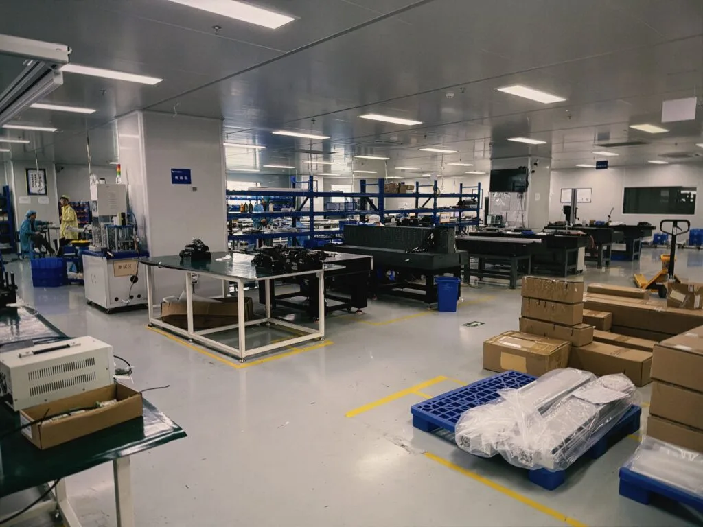
Cabinet space and wiring: what a gripper control box really occupies
A gripper control box is never the only device competing for rail space. It arrives with supply terminals, fusing, a fieldbus tap or IO slice, and a cable entry that needs bending room in front of it. In a finished cabinet it displaces whatever was drawn there first, and that displacement cascades into re-labelling and another panel revision.
- Depth, not just width. A deeper device pushes ducting forward and can block the swing of adjacent breakers.
- Clearance in front. Cable entry and diagnostics need hand access, which a dense panel does not have.
- Supply distribution. Every box needs a protected 24 V feed and a return path to the star point.
- Thermal load. Several small devices in one sealed enclosure raise internal temperature more than their ratings suggest.
Where the cabinet is genuinely full, an integrated gripper controller is not a convenience, it is the only arrangement that fits. Where there is spare rail and a trained panel builder, the space argument is weak and weight and service should decide instead.
Wrist weight and the payload you never got back
Robot payload ratings include the tool and the workpiece together. Anything outboard of the flange is subtracted from what the cell can carry, and with the worst leverage: mass far from the wrist axis raises inertia, which limits acceleration and therefore cycle time. On a cobot this is usually the binding constraint.
An integrated gripper controller puts electronics, heat path and connectors into the moving mass. A separate controller can sit on the frame, where weight is almost free. That is the strongest argument for keeping electronics off the wrist, and why a gripper with built-in controller is normally chosen on small tools handling small parts rather than on long-reach tools. The practical check is to compare flange mass against the rating with the heaviest workpiece, plus margin for cable and any wrist camera.
Where the drive electronics sit and what heat does to them
Motion produces heat in the drive stage, and the question is where it can go. With an integrated gripper controller the electronics share a body that carries motor current, so the housing is simultaneously a structural part, a heat sink and a surface facing the work area. In a separate arrangement the box sits in the cabinet, where air is filtered and managed.
| Condition | Integrated arrangement | Separate arrangement |
|---|---|---|
| High duty cycle | Heat builds in the tool body | Heat leaves through the panel |
| Enclosed or guarded cell | Ambient at the tool is the limit | Cabinet air is the limit |
| Near a hot process | Tool sees the radiant load | Box stays in the panel |
| Washdown area | Condensation risk on the tool | Box stays in controlled air |
Derating is the usual answer and an honest one: lower duty cycle, limited current, and the tool’s own mass acting as a heat sink for short bursts. Every one of those limits belongs in the specification of an integrated gripper controller before the order is placed.
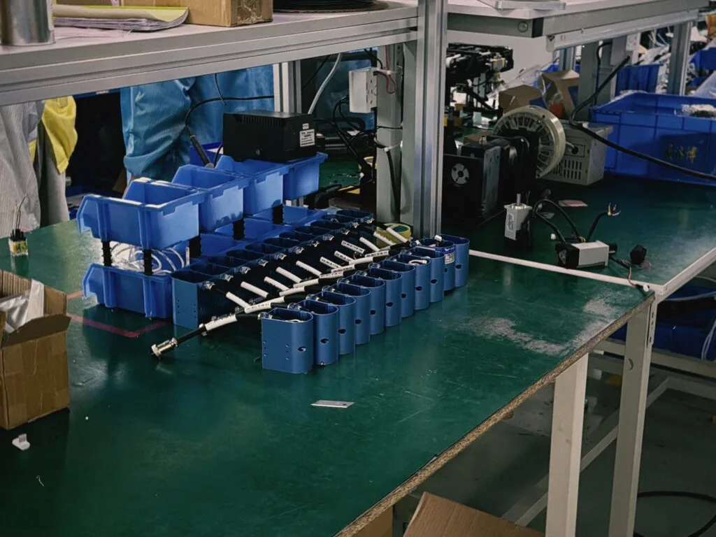
Cable routing: the moving-cable problem in both arrangements
Both arrangements have at least one moving cable, so the difference is not cable or no cable but how many and how long. An integrated gripper controller needs a single run to the wrist carrying supply and communication; a separate arrangement needs that run plus a longer cabinet-to-tool run for the control signal and power path.
Long runs are the ones that fail. They pass more joints and clamps, and more chances for a bend radius to be violated during commissioning when somebody pulls the loom tight to make the guarding fit. The failure is rarely a clean break; it is an intermittent contact that appears at one arm orientation and disappears when the technician arrives.
- Count connectors, not cables. Each plug pair at the wrist is where coolant, dust and vibration act.
- Keep strain relief on the fixed side. The tool end should not carry the weight of the dress package.
- Reserve a service loop. A tool change should not require re-terminating the loom.
Where the route is improvised, integration removes the long run but does not fix the wrist run, and that is where reliability is decided either way.
Commissioning and changeover: what differs at the machine
An integrated gripper controller moves configuration to the tool. Parameters, node address and scaling travel with the gripper, so a spare fitted at midnight comes up with the same setup as the unit it replaced, provided spares were configured before they went on the shelf. A separate arrangement keeps that identity in the cabinet: the gripper is simpler to swap, but the box must be told which tool is now attached.
The second difference appears on multi-product cells. With integrated electronics, two grippers hold two settings and changeover is a mechanical tool change plus a call to the right program. With one shared box, the box usually has to be re-parameterised unless a box is provided per gripper, and that second box brings the cabinet argument back.
Neither approach removes the need to record settings outside the machine. Protocol and addressing choices belong in that record and are worth settling early; the wider topic is covered in this note on gripper communication interfaces.
Maintenance implications: field-replaceable against factory-service
An integrated gripper controller is serviced as a unit. When the drive stage or electronics fail, the tool comes off the arm and a spare goes on, and the failed unit is diagnosed away from the cell. That gives a very short repair time if a configured spare is on the shelf, and a very long one if it is not.
A separate controller splits the fault domain. Most faults in a handling station are mechanical, and with electronics in the cabinet a mechanical fault is fixed by changing fingers or a jaw assembly without touching anything electrical.
| Scenario | Integrated arrangement | Separate arrangement |
|---|---|---|
| Electronics fault | Swap the whole tool | Swap the box or board |
| Mechanical fault | Swap the whole tool | Change fingers or jaws |
| Spares to hold | Configured gripper per type | One box plus fingers |
| Diagnosis location | Away from the cell | At the cabinet |
Choose by downtime cost, not parts count. A cell that stops the whole line justifies a configured spare of whichever unit is hardest to replace quickly. A station running alongside others tolerates a longer repair and is better served by the cheaper arrangement.
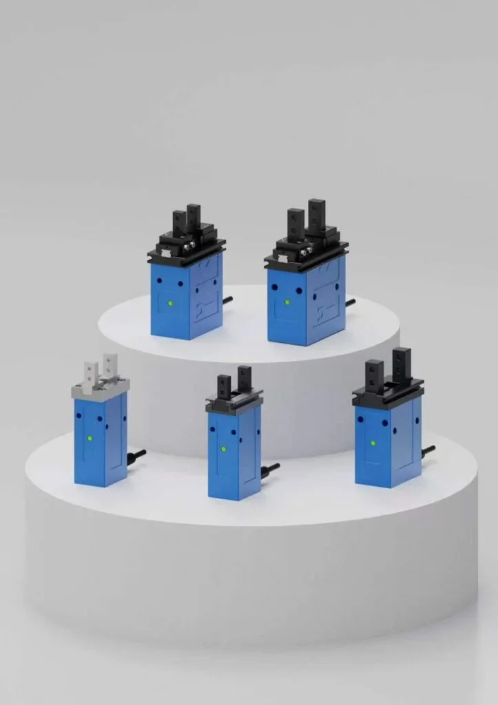
What fails first in an integrated gripper controller build
Failures cluster predictably once the arrangement is chosen. In an integrated design the first candidates are the wrist connector, the cable section immediately behind it, and the thermal margin. The connector sees every cycle and every cleaning operation, the cable behind it sees the tightest bend, and the thermal margin disappears first when production duty cycle turns out higher than the simulation.
The second cluster is configuration. A spare gripper never given an address, or given one that duplicates another tool on the same bus, produces a fault that looks electrical and is administrative. A written record of every node address prevents the most annoying class of fault in an integrated gripper controller installation.
The third is mechanical: finger wear, jaw play, debris in the guide. Integration does not change that, so the inspection routine should not change either.
What fails first when the controller is a separate unit
Here the first failures are in the link between box and tool. That run is longer, passes more joints and is often routed by whoever was available on the day. Terminal screws work loose under vibration, cable entries lose their gland seals, and a box mounted low collects whatever falls into it.
Cabinet fans and filters come next, because they have moving parts and are the components most often left off the maintenance schedule. A blocked filter raises internal temperature for every device in the panel, and the fault shows up on the device with the smallest margin, not necessarily the highest load.
Then the interface itself. If the box talks to the robot over digital IO, one mis-wired or degraded channel looks like a gripper fault and sends the technician to the wrong end of the machine. Clear labelling at the box and a signal check in the maintenance procedure remove most of that wasted time; the wiring and addressing options are described in the same note linked earlier on how gripper interfaces are wired and addressed.
Matching cell conditions to a controller arrangement
Read the cell, not the catalogue. These conditions decide more cases than any comparison of specifications, and most are known before a single gripper is ordered. They are also the fastest way to settle an argument that has stalled on an integrated gripper controller layout.
| Cell condition | Leans towards | Why |
|---|---|---|
| Cobot with thin payload margin | Separate, frame-mounted | Mass at the flange is the binding limit |
| Cartesian or gantry axis | Integrated gripper controller | Tool mass is carried by the axis |
| Cabinet already full | Integrated gripper controller | No rail space or entry clearance |
| Continuous high-duty gripping | Separate controller | Heat leaves through the panel |
| Frequent tool changes | Integrated gripper controller | Settings travel with the tool |
| No panel skills on site | Integrated gripper controller | Tool swap instead of wiring work |
| Several grippers on one arm | Separate controller per tool | One addressable device per gripper |
| Long run to a moving wrist | Integrated gripper controller | Removes the most exposed run |
Where the table disagrees with itself, weight and duty cycle normally decide. Both are measurable before the order and expensive to change afterwards.
Where an integrated gripper controller is the wrong choice
Integration is not a general upgrade, and the conditions where it makes the cell worse are worth naming plainly so the decision is not made by default.
- The payload margin is already thin. Added mass on the flange reduces acceleration and can force a slower cycle than the study assumed.
- Duty cycle is continuous. A tool that never rests must reject heat through its own body, in air that is often warmer than the cabinet.
- The tool sits in a hostile atmosphere. Washdown, fine dust or coolant mist act on the tool first, and it now holds the electronics too.
- Several grippers share one arm. Each integrated tool carries its own drive stage, multiplying the mass to be moved.
- Nobody on site can change a tool. An unfamiliar service action at the wrist makes repair slower, not faster.
An integrated gripper controller stops paying under these conditions and pays well under their opposites. On a project that reads like any of them, check the payload and thermal numbers before the specification is released.
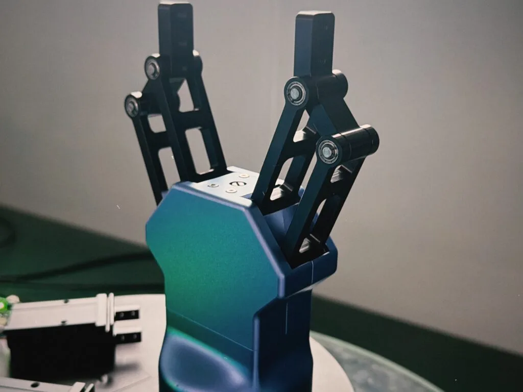
When a separate controller is still right
The separate arrangement keeps its place wherever weight, heat or service access decide the outcome. A frame-mounted box costs nothing in payload, sits in filtered air, and lets a mechanical fault be fixed with fingers and jaws rather than a whole tool. On a six-axis arm working at reach, that is usually the better engineering answer.
It also suits cells expected to grow. A controller with spare channels can take another gripper later without another cabinet device, whereas an integrated gripper controller scales by adding tools, each with its own electronics and mass. For small-part handling on a compact cobot the choice is often made on these grounds, as discussed in this guide to the best cobot gripper for small parts handling.
It suits teams that already know the equipment, too. A plant that maintains its own panels and keeps spares on the shelf will fix a separate unit faster than it will commission an unfamiliar integrated one.
Checklist before the integrated gripper controller decision is signed off
Work through these in writing. Each one changes the answer, and each is cheap to check before the order and expensive after it.
- Payload budget written out, including tool, heaviest workpiece and cable.
- Duty cycle and expected ambient at the tool, not at the panel.
- Cabinet rail space measured with entry clearance, not estimated from the drawing.
- Spare parts list agreed, including whether a configured spare tool can be shelved.
- Maintenance skill on site for the action the arrangement implies.
- Signal or network plan settled, with the addressing scheme written down.
- Tool change procedure drafted, including how settings are recorded and restored.
For EPGL-200-1200 electric gripper, request the current outline, mass, centre of gravity, mounting and electrical documents before assessing robot payload and installation. Review the controller arrangement, cable route and duty cycle for the supplied configuration.
Frequently asked questions
Is an integrated gripper controller always smaller than a separate one?
The electronics are smaller; the space claim is not necessarily. Integration removes the box but adds volume and a cable entry to the tool. What it reliably removes is rail space and entry clearance.
Does a gripper with built-in controller need a different cable to the robot?
It needs one cable to the wrist carrying supply and communication, instead of a signal cable to the cabinet plus a power path to the tool. The dress package gets simpler, but the cable still has to survive the same motion.
Can I mix the two arrangements in one cell?
Yes. A cell may use an integrated gripper controller on a small gantry axis where mass is free, and a separate gripper control box on a long-reach arm where every gram reduces acceleration.
How do I decide when the payload margin is too thin?
Add tool, workpiece, cable and anything else outboard of the flange, then compare against the rating with margin for the worst case. If the sum leaves less margin than the cycle study assumed, reduce acceleration before ordering.
Which arrangement gives a faster repair?
Integrated, if a configured spare is on the shelf, because the repair is a tool change. Separate, if the fault is mechanical, because fingers and jaws can be changed without touching electronics.
Is compact gripper integration worth it on a cartesian axis?
Often yes. On a linear axis the tool mass is carried by the axis rather than subtracted from a payload rating, so the weight penalty of an integrated gripper controller largely disappears.
Need help selecting a gripper?
Send your part drawing, robot model, required stroke, clamping force, country, and quantity for a practical model shortlist.