The gripper communication interface is the contract between the end effector and the cell controller: it fixes what the program can command, what comes back as evidence, and how fast a fault becomes visible. It is chosen while the cell is still a sketch, when changing it still costs nothing.
Most integration plans settle the gripper communication interface last, once the rack is full and the drag chain is closed, and the gripper then lives with whatever signals are left over. Working the other way round — required data first, wiring second, model third — removes a rework cycle later.
On this page
What the gripper communication interface actually decides
The choice settles four things at once, and they are not independent: changing the gripper communication interface later usually drags the other three with it.
- What can be commanded. A discrete signal asks for one stored grip; a serial command can ask for the position or force a specific part needs.
- What comes back as evidence. “The jaws stopped moving” and “the jaws stopped on a part” are different facts. Only the second proves a pick succeeded before the robot lifts.
- How the cell is wired. Discrete I/O pulls a bundle of conductors per axis through the drag chain; a serial pair carries the same information on two cores.
- What can be diagnosed while running. Counters, temperature and error codes let maintenance plan work instead of chasing a stopped line.
What each gripper communication interface carries
Gripper communication interfaces differ less in how they connect than in what they hold per cycle. The exact signal set always depends on the device and its manual.
| Interface | What it carries per cycle | Fits when | Main cost |
|---|---|---|---|
| Discrete digital I/O | A handful of on/off states | Fixed grip positions, one part family, fixed force | No position or force data; no diagnostics |
| Analogue setpoint | One continuous command value | Refitting an older cell that already has analogue cards | Calibration, drift and noise sensitivity |
| RS485 with a serial protocol | Commands plus position, force and status | Mixed part sizes, controlled force, per-cycle checks | Addressing and register mapping work |
| Modbus over serial or Ethernet | Register-based data on a documented map | Integrator wants an open protocol rather than a vendor library | Polling latency; map contents still vendor-specific |
| Fieldbus (EtherCAT, PROFINET, EtherNet/IP) | Cyclic process image plus acyclic parameters | The cell controller already runs that bus | Higher device cost and bus engineering |
Read it as a trade between information and integration effort: every step down the list carries more data and asks for more work. The useful question is not which gripper communication interface is most capable, but where extra data changes a decision the cell makes.
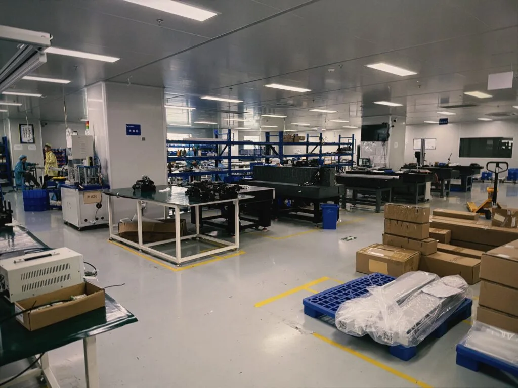
Digital I/O: what two signals can and cannot do
Discrete I/O is still the most common gripper communication interface in production: every controller understands it, it survives a decade in a cabinet, and a technician can trace it with a meter. The convention is usually 24 V DC with sinking or sourcing logic that must match the controller card.
- It cannot report where the jaws are. A single “closed” input looks the same whether the jaws closed on the part, on a chip of debris, or on each other with nothing between them.
- It cannot change force per part. Gripping one part gently and the next firmly needs a second stored recipe with a select line, or another interface.
- It cannot explain a fault. A fault bit says something is wrong, not whether the cause was supply, temperature or a stalled grip.
None of that automatically justifies a bus, and plenty of cells run for years on discrete signals without ever missing the data.
When simple I/O is enough
When the cell repeats one operation with little variation, a discrete gripper communication interface is usually enough. Five conditions decide it.
- One part family, stable gripped dimension. If the closing position never shifts, position feedback buys nothing.
- Grip position set at setup, not per cycle. Adjust once at changeover and leave it.
- Surfaces that tolerate a fixed closing force. No cosmetic face that needs the force lowered for one variant.
- Nothing to record or trend. Nobody asks how many cycles ran or how often a pick failed.
- Spare controller I/O already available. Adding a card can cost more than the interface upgrade.
| Signal | Direction | What it tells the cell |
|---|---|---|
| Grip command | Controller to gripper | Close using the stored setting |
| Release command | Controller to gripper | Open and clear the part |
| Motion complete | Gripper to controller | The jaws have stopped moving |
| Grip detected | Gripper to controller | The jaws stopped against a part, not against each other |
| Fault | Gripper to controller | Supply, temperature or internal error |
| Ready | Gripper to controller | Enabled and accepting commands |
| Recipe select | Controller to gripper | Use the second stored grip setting |
The row that ends most debates is “grip detected”. Where a cell must know a pick succeeded before it moves, that input decides whether discrete I/O is adequate or a serial gripper communication interface is necessary — and it is a question about the process, not the gripper.
Handshake and fault signals: the part most specifications skip
Two cells can share one gripper communication interface and behave very differently, because the handshake is a program decision rather than a wiring one. A grip command is followed by motion, then contact, then settling; read the state the moment the command is issued and the controller will occasionally see the gripper mid-travel and conclude the pick failed, or that it succeeded.
- Separate “finished” from “succeeded”. Completion is about motion; success is about contact and, where available, position within tolerance.
- Debounce deliberately. Status lines on any gripper communication interface can chatter at the moment of contact, and a short confirmation delay is cheaper than an intermittent fault.
- Define what the gripper communication interface does when the link drops. Hold, release or stay energised — different outcomes with different consequences. State the intended one so the integrator can test it rather than discover it.
- Make the fault line actionable. If nobody knows what the operator should do with a fault input, it is jumpered out within a month.
Data you gain from serial: position, force and diagnostics
Serial protocols turn the gripper from a device that receives commands into one that reports state. The short list below is what changes how a cell behaves.
| Data item | What it enables | Pays off when |
|---|---|---|
| Actual jaw position | Judging a grip from the position reached, not from a timer | Parts vary, or presentation scatters |
| Grip force or drive current | Handling delicate parts with a force chosen for them | Cosmetic surfaces and thin walls |
| Error and warning codes | Repairing without guessing which subsystem failed | Uptime matters more than device price |
| Cycle counter and temperature | Planning maintenance instead of reacting to it | Continuous duty and hard-to-reach cells |
| Device identity and firmware | Matching spares and keeping cells consistent | Several near-identical cells on one site |
One caution keeps this honest: reading data costs cycle time, so a cell that asks for everything every cycle can run slower than one that reads what it needs. A gripper communication interface that reports more than the process checks has moved work rather than removed it.
RS485 and Modbus: the practical middle ground
RS485 is a physical layer, not a protocol: a differential pair shared by several devices, which is why it tolerates the electrical noise of a machine frame better than a single-ended signal. On top of it most grippers speak a register-based protocol, very often Modbus RTU, with Modbus TCP over Ethernet where the cell already has a network. What makes this gripper communication interface the practical middle ground is that the protocol is public: no vendor library is needed, and a controls engineer can commission it from a manual.
- Node addressing. Every device on the segment needs a unique address; duplicates are the classic lost commissioning hour. Allocate addresses in the project file, not on site.
- Termination and reference. Bus ends are terminated and devices share a reference. Ignoring either produces faults that appear only while the machine runs.
- Polling latency. Serial polling is slower than a synchronous bus, which rarely matters because the closing loop is closed inside the gripper.
- Register map control. Record which map version each cell uses, so a firmware change cannot silently move a parameter.
Where a cell must react within a scan, RS485 is usually still adequate for gripping: the timing that matters is the gripper’s own response, not how often the controller reads it.
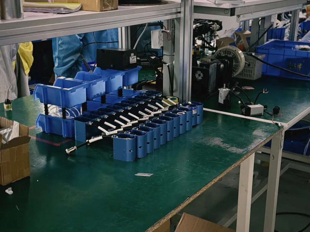
Fieldbus integration: EtherCAT, PROFINET and EtherNet/IP
When the cell already runs a fieldbus, the question changes: the gripper becomes a node of that network, so the gripper communication interface adds no I/O cards to the rack. The integration cost then sits in the device description file and the network configuration rather than in the hardware, and where the cell has no bus at all, adding one for a single gripper is hard to justify against RS485 on the same machine.
| Bus family | Typical host ecosystem | Device description file | Consideration |
|---|---|---|---|
| EtherCAT | Compact and PC-based controllers | ESI (XML) | Cyclic performance is the main attraction |
| PROFINET | Large PLC installations | GSD / GSDML | Widest device choice of the three |
| EtherNet/IP | North American PLC platforms | EDS | Built on standard Ethernet; common in mixed racks |
| Other buses (CC-Link IE, POWERLINK and similar) | Regional and machine-builder bases | Vendor tooling | Confirm device availability early |
Cyclic and acyclic traffic on the same cable
Bus-based gripper communication interfaces carry two kinds of traffic, and confusing them produces over-engineered specifications. Cyclic data is the small block exchanged every controller cycle; acyclic data is read or written when something changes.
| Traffic | Typical content | Refresh | Cost of a delay |
|---|---|---|---|
| Cyclic process data | Command, status word, setpoint, actual position | Every controller cycle | The gripper acts on a stale command |
| Acyclic parameters | Grip recipes, force limits, offsets | At start-up or on changeover | A new recipe is applied a moment late, once |
| Diagnostics and logs | Error history, temperature, counters | On demand | A fault is found later, not lost |
Keeping the cyclic block narrow is what keeps the network predictable: every byte added to it is exchanged on every cycle for the life of the machine, so parameters belong in the acyclic channel where they are written once.
Addressing, node count and wiring topology
Most commissioning problems with a gripper communication interface are mechanical or topological rather than protocol related, and all of them are cheaper to prevent on paper.
- Address plan first. Write every device address into the project file before the machine is powered, and leave gaps for the next axis.
- Spare capacity. One unused port, one unused node address and a metre of extra cable cost nothing now and a shutdown later.
- Cable rated for the application. Cable through a drag chain needs a continuous-flex rating, and the connector must survive the wrist. Static-rated cable fails where it bends, not at the connector.
- Topology honesty. Ethernet devices generally want a star through a switch. Daisy-chaining works only where the device provides the second port and the network is configured for it.
Where the gripper travels with the arm, the cable and its connector are part of the gripper communication interface decision and belong in the same conversation.
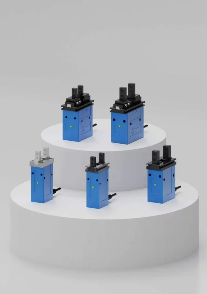
Deciding early to avoid rework
The gripper communication interface belongs in the first technical exchange, alongside the stroke range and the force requirement. Placed at commissioning instead, it triggers a chain nobody enjoys explaining: an extra I/O card and a rack change, a new cable and a reopened drag chain, a robot program retested against a new status scheme, and an unplanned validation round.
- State the interface in the specification. Protocol or signal set, connector, cable length, and the data the cell needs — not just the word “gripper”.
- Say who controls it. Robot, PLC or safety controller. That answer decides the network and the address plan.
- List the data, not the features. “Position readback after grip, before lift” is a requirement; “advanced communication” is not.
- Request the documentation before the order. Register map or device description file, signal list, failure behaviour. If the integrator cannot read it beforehand, it will be discovered on site.
The gripper communication interface also constrains the shortlist in ways that are easy to miss: a cell needing per-part force and position confirmation has already excluded every discrete-only model. The wider selection logic — stroke, force, weight and mounting together — is set out in how to choose an electric gripper for a robot arm.
Worked example: interface notes for one pick-and-place cell
The following is an illustrative derivation, not a specification for any model. Suppose a cell loads three similar housings, roughly 40 to 55 mm across the gripped flats, one variant carrying a cosmetic face, and the existing PLC has no fieldbus but does have spare serial ports and a few free digital channels.
| Requirement | What covers it | Why not the simpler alternative |
|---|---|---|
| One part family, close in size | Digital I/O with grip detection | Alone it cannot handle the third variant’s force setting |
| Grip position differs per variant | Stored recipe selected over serial | A single fixed I/O position forces a compromise on one part |
| Cosmetic face on one variant | Force command, lowered for that part only | Discrete I/O cannot set force at all |
| No fieldbus in the cell | RS485 to the existing PLC port | A new bus for one device is hard to justify |
| Faults must be attributable | Serial error codes | A single fault bit reports only that something failed |
| Spares across two cells | Device identity read at start-up | I/O leaves version control to paperwork |
Two things generalise. The deciding factor was one cosmetic-face part, not the part count, and the gripper communication interface stayed on the cheap side of the trade: serial over the port the cell already had. Where force and closing behaviour sit in the same picture is covered under gripping force and electric gripper stroke.
Interface checklist before the cell is built
Every item below concerns the gripper communication interface and can be answered from the cell layout, the controller documentation and the process sheet, with no vendor meeting required.
- Is the gripper communication interface named in the specification? Protocol or signal set, connector type, cable length and cable rating for the axis.
- Which device owns the gripper? Robot, PLC or safety controller, with a defined address plan and a spare node allocated.
- Is the required data listed per step? What the cell must know before lift, before place, and after release.
- Is the handshake defined? Completion, contact confirmation and settle delay stated separately.
- Is loss-of-communication behaviour agreed in writing? Hold, release or remain energised — and tested.
- Is the documentation on hand before the order? Register map or device description file, signal list, fault code list.
EPGC-50-150 lists I/O or Modbus RTU (RS485) as catalog interface options. Confirm the supplied configuration and request its register map, available status signals and fault-handling instructions before programming.
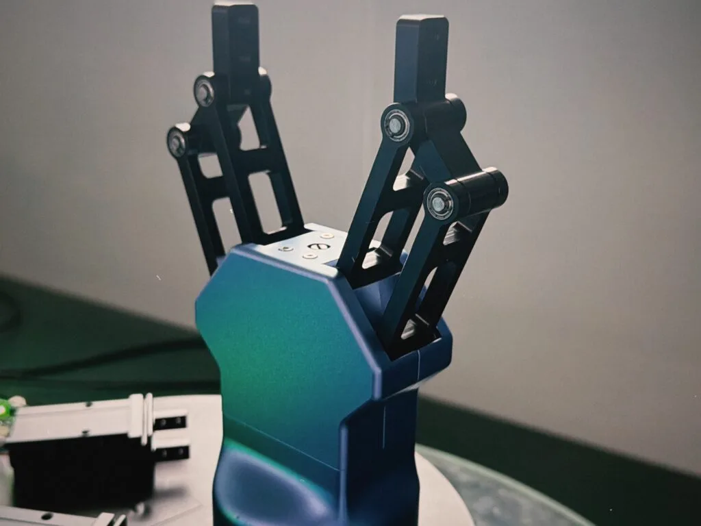
Frequently asked questions
How do I choose between digital I/O and a serial gripper communication interface?
Start from the data the cell needs before it lifts the part. If a fixed closing position and a grip-detected input answer every question the program asks, the simpler gripper communication interface is discrete I/O. If the closing position or the force must change between parts, serial is cheaper over the life of the cell.
Is Modbus fast enough for a gripper?
For a gripper communication interface over serial, usually yes. The closing motion and the force limit are handled inside the gripper, so the controller asks for a result rather than closing a fast loop. Polling latency matters when several devices share one segment and the program expects an answer within a scan; on a quiet segment it is normally far shorter than a pick cycle.
Do I need position readback if the robot already knows the sequence?
The robot knows what it commanded, not what happened. A gripper communication interface that reports only completion carries a failed pick through the same motions, turning a missing part into a downstream fault. Position readback lets the program verify the grip before the move, which separates a detected mispick from a mystery further down the line.
What should happen to the part if communication drops?
That decision must be deliberate, because the outcomes differ: holding position keeps the part but may mean staying energised, releasing drops it, and driving a stalled grip generates heat for no result. The gripper communication interface should therefore be specified with a stated failure behaviour, confirmed by the documentation and tested by the integrator.
Can a fieldbus gripper be added to a cell with no fieldbus?
It can, and it is rarely worth it for one device. Adding a bus means network configuration, a master or scanner, a process image layout and an address plan, work that pays back only when several devices share it. Where the cell has spare serial ports, RS485 with a documented register map delivers most of the data for a fraction of that engineering.
Need help selecting a gripper?
Send your part drawing, robot model, required stroke, clamping force, country, and quantity for a practical model shortlist.
Compare model interfaces
EPGS-6-10 lists I/O control. EPG2-100-50 lists I/O (NPN) or Modbus RTU (RS485). Ask for the current interface configuration and pinout of EPGL-200-1200.