EPG2-50-150 Electric Gripper
EPG2-50-150 is listed in the EPG2 series for industrial automation. Listed control: I/O (NPN) or Modbus RTU (RS485). Compare the model data with your workpiece and installation requirements.
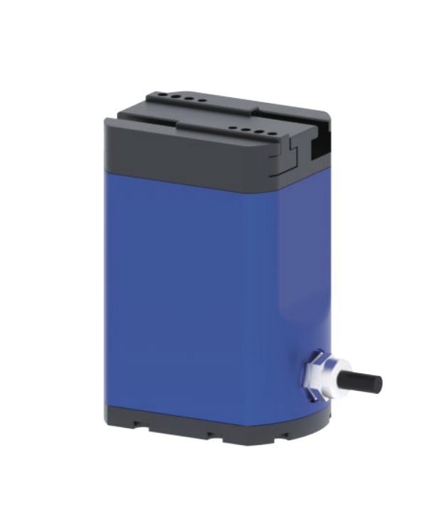
Technical profile and model data
Overview
Use the checks below to review EPG2-50-150 against your workpiece, tooling and controller.
- Check the part shape, contact arrangement and finger travel for this model.
- Confirm force conditions, finger length and retention through acceleration.
- Request current specifications and include any drawings or wiring information you need.
Technical specifications
| Max. working stroke | 0–50 mm |
|---|---|
| Rated gripping force | 40–150 N |
| Max. recommended clamping load | 3 kg |
| Open/close time (one way) | 0.5 s |
| Machine weight | On request |
| Operating voltage | 24 V DC ±10% |
| Communication | I/O (NPN) or Modbus RTU (RS485) |
| Positional repeatability | ±0.02 mm |
| Sustained current | 0.6 A |
| Power-off brake | Confirm configuration at quotation |
| Dimensions | 66 × 53 × 103.5 mm |
| IP grade | IP40 |
| Certification | Certificates available on request |
| Operating environment | 0–40 °C, 20–85% RH |
Confirm the stroke definition, force conditions, finger design and workpiece before ordering. Request current values for unlisted fields.
Detailed description, features, and application notes
EPG2-50-150 is a two-finger parallel electric gripper for higher force applications. The published model data lists 0–50 mm maximum working stroke, 40–150 N Rated gripping force and 3 kg maximum recommended clamping load. Use these values for an initial shortlist, then confirm finger design and the current drawing for the supplied configuration.
Looking for a DH-Robotics PGE alternative to the PGE-100-26? See how the EPG2-50-150 compares.
Check the workpiece and control
Compare the full part size range with the gripper opening and finger clearance. Check part mass, material, surface contact and motion through the full cycle. The listed communication is I/O (NPN) or Modbus RTU (RS485). Confirm the controller wiring and mounting envelope before ordering.
What to send for selection
- Part drawing or dimensions, mass, material and contact surfaces.
- Robot or machine model, mounting space and finger arrangement.
- Motion or rotation requirements, cycle target and control interface.
For the selection method, see How to choose an electric gripper, gripping force, stroke and finger design.
Model questions
What stroke and force are listed for EPG2-50-150?
0–50 mm maximum working stroke and 40–150 N Rated gripping force. Confirm the measurement conditions against your part and fingers.
What is the maximum recommended clamping load?
3 kg. Include acceleration, contact position and finger length in the application review.
Which control interface is listed?
I/O (NPN) or Modbus RTU (RS485). Ask for the matching pinout and controller documentation with your enquiry.
- Typical lead time: 7 days, confirm on quote
- 12-month warranty
Need drawings, parameter sheets, or controller notes?
Ask for the current model-specific drawings, specifications and controller notes. Include the model, robot or controller, application, quantity and destination country.
Application checks for EPG2-50-150
Confirm finger design, part contact area, cycle time, and robot payload before final selection.
Model questions
Which control interface is listed?
I/O (NPN) or Modbus RTU (RS485). Confirm the supplied pinout and controller configuration for this model.
What supply voltage is listed?
24 V DC ±10%. Check the current wiring document for the supplied configuration.
What protection rating is listed?
IP40. Confirm suitability for your actual environment.
How should the fingertips be selected?
Match the fingertips to the part geometry, contact surfaces and required force. Send the part drawing for application review. See our finger design guide.
Before quotation
Send part size, part weight, robot model, finger length, cycle time, destination country, and quantity.
Related selection and integration guides
For a new cell or a retrofit, review the tradeoffs between electric and pneumatic grippers. If your controller uses serial communication, the RS485 and Modbus wiring guide outlines the verification process; confirm this model’s interface and register map before wiring.