A gripper drops parts at speed because the grip was sized for a stationary load, not for the acceleration the robot actually applies. The part that hangs safely between the jaws during a slow dry run is thrown at those same jaws once the cell runs at cycle time, and every unit of acceleration multiplies the force the fingers must resist. A gripper drops parts mid-move for reasons that repeat across machines: a dynamic load nobody calculated, a contact surface with little friction, and a force or timing value left at whatever got the cell through commissioning.
This note is a fault-finding order, not a list of settings to try. The reasons the gripper drops parts separate cleanly into mechanics, contact and control.
On this page
Why the gripper drops parts at speed but holds at low speed
Speed changes nothing about the force a gripper can produce. It changes the load path. At a slow jog gravity is the only load and almost any contact carries the part. At production speed the same part is accelerated along the path, decelerated at the end of it and swung through wrist rotation, and each phase adds a load the static grip never resisted.
So the first question is not how much force the gripper is set to, but at which moment the part leaves the jaws. A gripper drops parts just after a direction change far more often than at constant velocity, because that is where the load reverses and the part starts moving relative to the pads.
- Drop at the start of the move. The load appears as the axis accelerates, and the grip was never loaded that way during the dry run.
- Drop at the end of the move. Deceleration plus residual swing loads the jaws harder than acceleration, and it is often the sharper ramp.
- Drop at hand-off. The receiving fixture moves while the gripper still holds the part, pushing it sideways out of the pads. This is the case where the gripper drops parts with both tools apparently working.
Dynamic load versus static load
The load a grip resists is part mass multiplied by the acceleration it sees, not by gravity alone. On a cell that starts and stops quickly that product can be several times the part weight, and it acts along the path rather than downward. Friction between pads and part converts closing force into resistance to that load, which is why the same gripper drops parts on one station and holds on another.
The required force is estimated from part mass, peak acceleration, friction at the contact and the number of contact faces, then a margin is added because friction falls as pads wear. Two of those four inputs are usually unknown at commissioning, which is why the setting ends up too low. Without that margin the gripper drops parts the first time a batch arrives heavier than the sample.
| What changes as the axis speeds up | Slow jog | Production speed |
|---|---|---|
| Load the grip resists | Part weight only | Weight plus inertial load along the path |
| Dominant load direction | Downward through the pads | Sideways, resisted by friction alone |
| Worst moment in the cycle | None in particular | Peak deceleration, then tool rotation |
| Failure signature | Part shifts in the jaws but stays put | Part leaves the jaws with no warning |
| What to check first | Contact marks on the part | Whether the gripper drops parts on every recipe or only the fastest |
Friction and surface condition
A gripper that looks like it drops parts because force is low is often dropping them because friction is low. Friction depends on the material pair, the part finish and whatever sits on that surface. Machined steel on a hardened steel pad has very little to grip; the same part on a polyurethane pad has much more.
Contact pressure matters as much as pad material: a small hard pad makes high pressure, can mark the part and still slide. When the gripper drops parts repeatedly on one station, read the pad faces before touching a parameter. A pad that has gone glossy is the most common reason a gripper drops parts on a station that used to run clean.
| Contact pair | Friction behaviour | What happens at speed |
|---|---|---|
| Hardened steel pad on machined steel | Low | Part slides in the jaws and gets marked |
| Polyurethane pad on painted sheet | Moderate to high | Grip holds, but the pad compresses and the part settles |
| Serrated jaw on cast aluminium | High, mechanical engagement | Holds well, leaves witness marks, unsuitable for finished faces |
| Flat pad on an oily or wet part | Low and unpredictable | Intermittent drops that track the coolant, not the program |
| Soft rubber pad on polished parts | Moderate | Holds until the pad picks up dust, then the gripper drops parts |
Wrong finger profile and contact geometry
Fingers are the real interface between gripper and part, and geometry that holds a part on the bench can lose it under load. Flat pads on a cylindrical part touch along a line, so the part can roll out sideways; a conformal or V-shaped pocket removes that freedom. Contact near the jaw root gives almost no lever arm, so part variation shows up as a force change instead of a position change. Fingers that are long relative to their section deflect and lose contact pressure exactly when the dynamic load peaks.
The subtler case is a profile that grips only near the end of the closing stroke. The jaws then have no travel left to absorb a part slightly larger than nominal, and the force delivered is lower than the setting suggests — which is why the gripper drops parts that a mid-stroke grip on the same tool would have held.
Programmed force that is too low for the move
Most cells are set up during a dry run at reduced speed, and the force value written then is rarely revisited. A value confirmed on a stationary part can be inadequate at cycle time, and programmable force makes that easy to fix and easy to forget.
Two mechanisms cause drops that look mechanical. The first is a correct force applied too late: if the move starts while force is still ramping, the first part of the acceleration is carried by a partly closed grip. The second is a force that suits the nominal part but not the heaviest part in the batch. Both show up as a gripper drops parts only on some shifts.
Before raising the setting, confirm what the part will accept, because an increase that deforms or marks the part is a second defect rather than a fix. Where the requirement approaches the part limit, contact geometry beats pressure, as set out in this note on how gripping force is specified.
Grip timing and the grip-confirm signal
A grip sequence has four events: the close command, the jaws reaching the part, force reaching its set value, and confirmation that a grip exists. The move must start after the last of those. When the gripper drops parts just after a pick, the gap between those events is where the fault lives.
Two timing faults are common. In the first, a fixed delay replaces the grip-confirm input, and the delay was tuned on a warm machine with a well-presented part. In the second, the input is wired and read, but the controller samples it once per scan and the axis changes state before the next, so the axis accelerates while the grip is still settling.
Settle time matters at the end of the stroke too, because jaws that stop moving can still relax as the part beds in. Where the grip sits near the end of travel, this note on electric gripper stroke is worth reading first.
Mechanical faults that look like control faults
Not every intermittent drop is a parameter, and several mechanical conditions produce the same symptom and survive any amount of program tuning.
- Worn or glazed pads. Friction falls gradually until a batch runs fast enough that the gripper drops parts.
- Loose mounting fasteners. The body shifts under load, changing jaw position and throwing the part sideways at hand-off.
- Cable or hose drag at the wrist. A cable that tightens at one wrist angle disturbs the grip, so the gripper drops parts at exactly that point in the path.
- Contamination. Chips, dust or dried coolant on the pad faces act like a low-friction shim.
- Hot parts. Heat through the fingers softens pads and reduces friction over a shift.
- Fixture interference. The part exits because something downstream touches it.
One test separates these from a control fault. Run the same part through the same path at low speed and at cycle speed, then compare the marks the pads left. Different marks mean the part moved in the jaws; identical marks mean the gripper drops parts because of an external force or a timing fault, not because the grip failed.
A diagnostic sequence when the gripper drops parts
Work through the steps in order and stop at the first one that reproduces the fault. The order eliminates the expensive answers first rather than finding the quickest change.
- Reproduce it deliberately. Step the cycle speed up until the part drops and note the threshold. A defined threshold suggests a load problem; a random fault suggests timing or contamination.
- Mark the part. A pencil line across the contact shows whether the part slid or left cleanly.
- Log the moment. Acceleration, deceleration, rotation or hand-off.
- Check the grip-confirm input. Confirm the move waits for it rather than for a delay.
- Inspect the pads. Look for glazing, embedded chips and uneven wear between fingers.
- Repeat with a heavier and a lighter part. If the threshold moves with weight, the limit is force or friction; if it does not move at all, look at geometry and timing. A gripper drops parts on both weights with no change in threshold, which points away from load.
- Repeat with a different surface condition. Clean against oily separates a friction limit from a force limit.
- Change one parameter at a time and record the value, so the next engineer can see what was tried.
| Symptom | Most likely cause | First test |
|---|---|---|
| The gripper drops parts only on the fastest recipe | Force margin too thin for the dynamic load | Step the speed and find the threshold |
| Drops on one station, all recipes | Low friction at the contact pair | Clean the pads and repeat with a dry part |
| Drops at one wrist angle only | Cable or hose drag on the tool | Re-dress the cable and repeat the path |
| The gripper drops parts just after the close command | Move started before the grip was confirmed | Trace the grip input against the move command |
| Marks appear in different places each cycle | Part slipping in the jaws | Measure the contact position in the stroke |
What to record before you change anything
Most time lost on a fault where the gripper drops parts comes from an incomplete record, because the original conditions are rarely reproducible a week later. A record that omits the speed makes a gripper drops parts fault impossible to reproduce.
| Record | Why it decides the answer |
|---|---|
| Axis speed, acceleration and deceleration settings | Define the dynamic load the grip had to carry |
| Force setting in the program | Separates a force limit from a friction limit |
| Source of the grip confirmation | Input, fixed delay, or nothing at all |
| Part weight and surface condition | The two inputs that change between batches |
| Pad type, age and wear pattern | Shows whether friction has degraded over time |
| Point in the path where the part is lost | Acceleration, deceleration, rotation or hand-off |
| What changed since it last worked | Pad change, program edit, new batch, new operator |
Fixes ranked by effort and effect
The fixes below are ordered by effort; the cheap ones also make the diagnosis cleaner when a gripper drops parts, but only the last two address a genuine design limit.
| Fix | Effort | Effect | When it is the right answer |
|---|---|---|---|
| Clean or replace the pads | Very low | High | Pad faces are glazed, marked or contaminated |
| Add a verified dwell before the move | Low | High on intermittent drops | The drop follows the close command closely |
| Raise the force setting with a margin | Low | High if friction is adequate | The part tolerates more force without marking |
| Re-profile the acceleration and deceleration ramps | Low to moderate | Moderate to high | The threshold speed sits close to the cycle requirement |
| Slow the cycle as a stopgap | Very low | Temporary | The gripper drops parts and the line cannot stop for a fix |
| Change pad material or hardness | Moderate | High | Friction is the limit and the part cannot take more force |
| Redesign the finger contact geometry | Moderate | High | The part rolls or slides because contact is a line or a point |
| Use a gripper with force and position feedback | High | High | Drops must be detected rather than tolerated |
When the fix belongs in the specification
If the sequence ends with a force setting already near the top of its range, pads that cannot be made grippier and a cycle time that cannot be relaxed, the cell is asking for more than the gripper was selected for. That is a specification problem, and it is cheaper on paper than on the line.
Three specification items decide whether the next gripper drops parts under the same conditions. Force headroom comes first: choose a margin above the calculated requirement, not the requirement itself, because the friction input is an estimate. Feedback comes second, because a gripper that reports position and force lets the controller verify the grip before it moves instead of discovering the loss at the destination. Force headroom is the cheapest of the three to write down, and it is the one that decides whether the gripper drops parts on a heavier part next year.
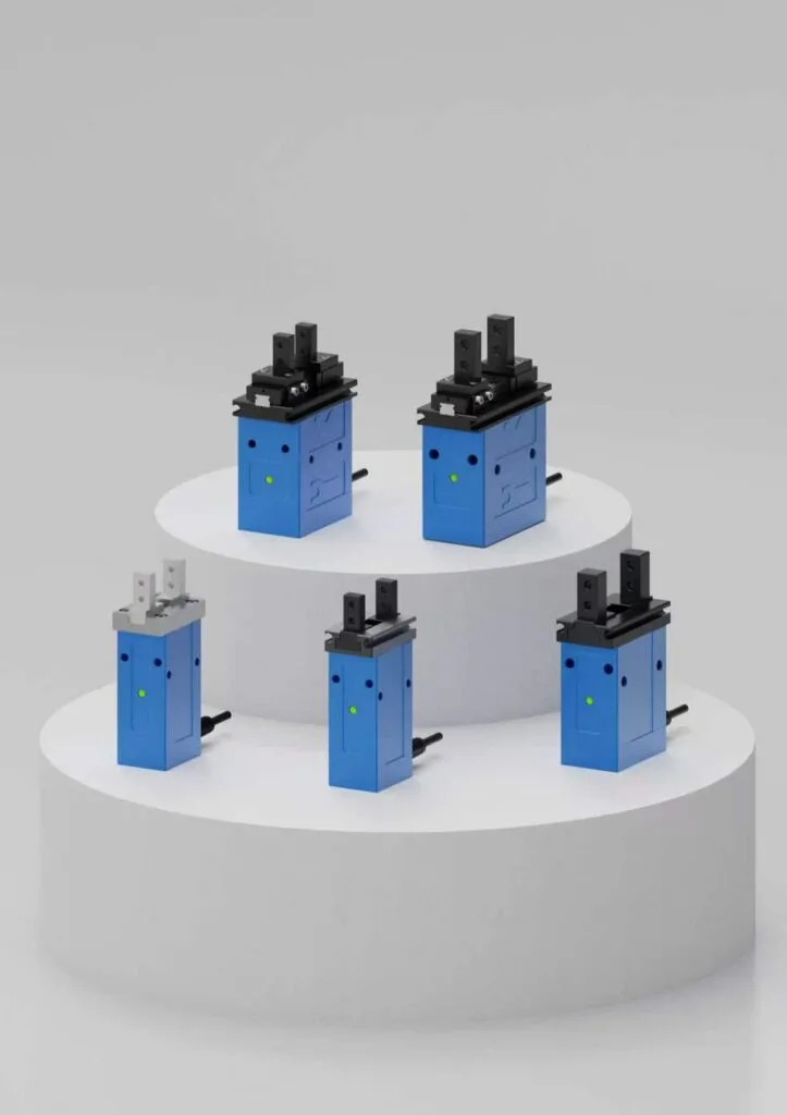
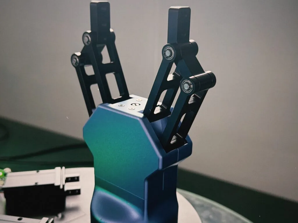
For EPGL-200-1200 electric gripper or EPG2-100-50 electric gripper, review the published reference values together with the proposed fingers, contact layout, workpiece mass and acceleration. Confirm retention for the actual transfer path. Use the checks in choosing an electric gripper for a robot arm to prepare the review.
Checklist before the cell returns to production
- Pad condition and contact marks checked on a marked part, not by eye alone
- Grip-confirm input traced and confirmed to precede the move command
- Force setting recorded with the part weight it was verified against
- Acceleration and deceleration ramps recorded so the next change is visible
- Full-speed test with the heaviest and lightest part in the batch
- Repeat test on the first part after warm-up and after a pad change
- Agreed action in the maintenance notes if the gripper drops parts again
When the gripper is not the cause
Some drops are diagnosed as a grip fault and are nothing of the sort. If a part drops only when one upstream station runs, the trigger is part presentation. If it always happens at the same waypoint in a long path, axis tuning or a path singularity is a better suspect than the tool. If two grippers hand a part to each other, the fault usually sits in a window where neither grip is fully established.
The distinguishing question is whether the part leaves jaws that are still closed. A part released correctly but missing at the destination is a fixture, path or program problem, and no gripper specification will change that outcome.
Frequently asked questions
Why does a gripper that drops parts behave differently at low speed?
Because load, friction and timing interact, and the margin is smallest on the heaviest part in the batch at the fastest recipe. The gripper drops parts at a threshold rather than all at once, so the fault looks random until the threshold is measured.
How do I tell whether the problem is force or friction?
Change one condition at a time. Repeat the cycle with a clean dry part and with the same part lightly oiled. If the threshold moves a long way, friction is the limit and a pad or geometry change helps more than more force. A gripper losing grip only on oily parts points at the contact pair rather than at the mechanism. If a gripper drops parts on oily parts but not on dry ones, the contact pair is the constraint.
Can I just raise the gripping force and be done with it?
Sometimes, and only if the higher force stays within what the part accepts. A higher setting reduces the margin left for variation in friction and can mark, deform or work-harden the part. It also masks pad wear, so the same gripper acceleration problem returns later with less warning.
Should I slow the robot down instead?
As a temporary measure while a fix is prepared, yes. As a permanent answer, no. Every cycle at reduced acceleration costs throughput and leaves the underlying margin problem in place. Thinning the acceleration ramp is worth testing, because the gripper drops parts on the sharper of the two ramps more often than at the higher speed.
What feedback catches a slip before the part is lost?
At minimum, a grip confirmation that reflects an actual grip rather than the end of a closing command, so the move cannot start on a bad grip. Beyond that, position and force feedback let the controller compare the achieved grip against the expected one and stop the cycle when they differ.
Need help selecting a gripper?
Send your part drawing, robot model, required stroke, clamping force, country, and quantity for a practical model shortlist.