On this page
Loading a CNC machine is a different job from moving a finished part across a bench, and most gripper problems in machine tending come from treating the two as the same task. The gripper has to survive chips, coolant, a moving door, a tight fixture envelope and a repeatable seating requirement, and it has to do all of that inside the same cycle time the previous pneumatic unit achieved. Gripping force is rarely what limits the cell.
Machine tending cells fail for predictable reasons, and they are almost never the reasons the original selection focused on. The constraints below are ordered roughly by how often they cause trouble in practice.
Why the machine environment changes the selection
A pick-and-place gripper works in clean air with a defined approach path. A machine tending gripper works inside a process that is actively hostile to precision mechanisms: metal is being cut, fluid is being thrown, and a door is opening and closing several times a minute. Anything that enters that envelope needs to tolerate the environment first and perform the grip second.
The practical consequence is that two grippers with identical stroke and force ratings can behave completely differently in service. The difference is usually sealing, finger geometry and how the cable enters the tool — not the datasheet numbers.
The failure modes that show up first
Across turning and milling cells, the same handful of problems recur. Recognising the symptom early is worth more than any specification comparison.
| Symptom | Usual cause | What to change |
|---|---|---|
| Jaw stalls or jams part-way through the stroke | Chips packed into the guide rail or around the jaw carriage | Add wiper seals, re-direct coolant nozzles away from the load path, consider an air purge on the gripper body |
| Part slips during rapid traverse | Acceleration load exceeds available friction, or finger profile contacts only a small area | Re-check the dynamic rather than static requirement, and widen the contact area before raising commanded force |
| Part seats inconsistently in the chuck | Tool frame drift, adapter runout, or a finger profile that allows the part to cock | Re-teach the tool frame, indicate the adapter, and add a locating feature to the finger |
| Grip confirmation becomes intermittent | Coolant ingress at the connector, or a cable service loop that has fatigued | Improve ingress protection at the electrical interface and re-route the service loop |
| Repeatability degrades over months | Wear on the finger contact faces, not on the gripper mechanism | Treat fingers as a consumable with a measured replacement interval |
Note how few of these are solved by buying a stronger gripper. Only the second one touches force at all, and even there the fix is usually contact geometry.
Chips and coolant: what protection actually buys you
Ingress protection ratings describe resistance to dust and water under defined test conditions. They do not describe resistance to a stream of aluminium chips mixed with cutting fluid at pressure, which is the actual condition inside a machining centre. A higher IP rating is helpful and worth paying for, but it is not a substitute for keeping the chips away from the mechanism in the first place.
Three measures do most of the work:
- Physical shielding. A simple deflector plate above the jaw carriage stops most of the chip load before it reaches the seal. It costs almost nothing and is often the single most effective change.
- Seal selection. Wiper seals that scrape the rail on every stroke tolerate contamination far better than simple lip seals, because they clear debris rather than trapping it.
- Air purge. A small positive pressure inside the body keeps fluid and fines moving outward. It requires an air line at the wrist, which is a real integration cost and should be decided early.
Where coolant is directed straight at the load path, re-aiming the nozzle is often easier than upgrading the gripper. This is a machine-side fix, not a gripper-side one.
Fitting through the door and into the chuck
The approach envelope usually constrains the design more than the grip does. A gripper that performs perfectly on a bench can be unusable in a cell simply because it cannot reach the part without the fingers or the body fouling something on the way in.
| Constraint | What it forces | Practical implication |
|---|---|---|
| Door opening height and width | Limited approach angle | Fingers may need to enter parallel to the spindle axis rather than from above |
| Chuck bore or collet depth | Finger reach beyond the body | Long fingers trade reach for stiffness; expect deflection under load |
| Fixture and tool clearance | Finger thickness limit | Thin fingers on a wide-stroke gripper is the classic stiffness compromise |
| Rail and tailstock position | Retract clearance | The open position must clear the machine, not just the part |
| Door interlock timing | Cycle time budget | Slow gripper motion may cost more than the grip itself |
The point worth carrying away is that open-stroke clearance must be checked against the machine envelope, not against the part. Many integration problems trace back to a gripper that grips correctly but cannot retract without touching the door frame.
Finger design for turned and milled parts
Fingers do more of the work in machine tending than the gripper body does. They determine contact pressure, wear rate, and whether a chip can lodge in the contact area.
| Finger contact material | Wear behaviour | Fits well when | Poor fit when |
|---|---|---|---|
| Hardened steel, plain | Very durable, low compliance | Rough or as-cast surfaces, high cycle counts | Finished surfaces where marking matters |
| Aluminium | Wears faster, sacrificial | Light parts, short runs, prototype cells | High-volume production with abrasive parts |
| Urethane or rubber pad | Pads wear, fingers do not | Finished surfaces, moderate force | Hot parts, or where chips embed in the pad |
| Engineering plastic (for example PEEK) | Good wear with low marking | Delicate finished surfaces, moderate temperature | Heavy parts or sharp edges |
A practical rule: if the part surface is the customer’s finished product, the finger wear part should be softer than the part. If the part is a blank that will be machined further, the finger should be hard and the part can take the marking.
Force and stroke trade-offs in a machine cell
Two assumptions cause most oversizing. The first is that more force is always safer. In a chuck loading application the part is often thin-walled or already finished on one side, and excess clamping force deforms it — which then shows up as a concentricity problem attributed to the machine. The relevant question is the minimum force that holds the part through the worst acceleration in the cycle, plus a margin, and no more.
The second assumption is that more stroke is always better. Stroke is bought with body length and with finger stiffness. A wide-stroke parallel gripper is the right answer when part families vary a lot, but in a single-product cell it usually just adds mass at the wrist and deflection at the fingertips. Where the parts vary, programmable stroke lets one tool cover the family without a mechanical change over.
The general selection logic is set out in how to choose an electric gripper for a robot arm, and the force reasoning specifically is covered in the article on gripping force specification.
Part temperature and cycle time
Parts coming straight off a machining operation are warm, and in some processes — heavy turning, or a part that has just come out of a wash station — they are hot enough to matter. Heat affects the finger material more than the gripper body, since the fingers are in direct contact and are often thin. Urethane pads are the first thing to suffer; hardened steel and engineering plastics hold up better.
Cycle time is the other constraint that gets discovered late. An electric gripper can be configured for position and speed, which means a slow, gentle approach can be used where the part is delicate and a fast one where it is not. That flexibility is genuinely useful in a cell running several part numbers, but it has to be programmed deliberately — the default profile is rarely the fastest one that is still safe.
When electric gripping is not the right answer
Electric grippers suit machine tending well because force and position are repeatable and adjustable, and because the feedback can confirm a grip without extra sensors. There are still cases where they are the wrong choice:
- Very large or very heavy workpieces, where the required force per unit of wrist mass pushes the design toward hydraulic or pneumatic actuation.
- Extreme temperature near the part, beyond what the finger and seal materials tolerate.
- Cells with no electrical path to the wrist that will not be re-cabled, where a pneumatic unit may be the pragmatic answer. The trade-offs are compared in electric gripper vs pneumatic gripper.
Being honest about these cases saves a rebuild later. A gripper that is correct for the application beats a gripper that is technically more advanced.
Frequently asked questions
How do I stop chips from getting into the gripper jaws?
Start with a deflector plate and a wiper seal, then look at coolant aim. Air purge helps in stubborn cases but adds an air line at the wrist, so treat it as a design decision rather than a retrofit.
Is higher IP rating always better for a CNC cell?
It helps, but the rating is measured under controlled conditions that do not match a chip-and-coolant stream. Physical shielding and good seal design usually matter more than the published number.
How much clamping force do I actually need for turning?
Enough to hold the part through the highest acceleration in the move, with a margin, and no more. Excess force on thin-walled or finished parts causes deformation that gets misread as a machine accuracy problem.
Should I use hard or soft fingers?
Match the finger to the surface that matters. Soft contact for finished surfaces, hard contact for blanks and rough castings where durability and chip resistance dominate.
Can an electric gripper match the cycle time of the pneumatic unit it replaces?
Usually yes, because position and speed profiles can be tuned per part number. The gain depends on programming the profile rather than accepting the default, and on how much of the cycle was actually spent gripping.
Image reference
Series to review for heavier parts
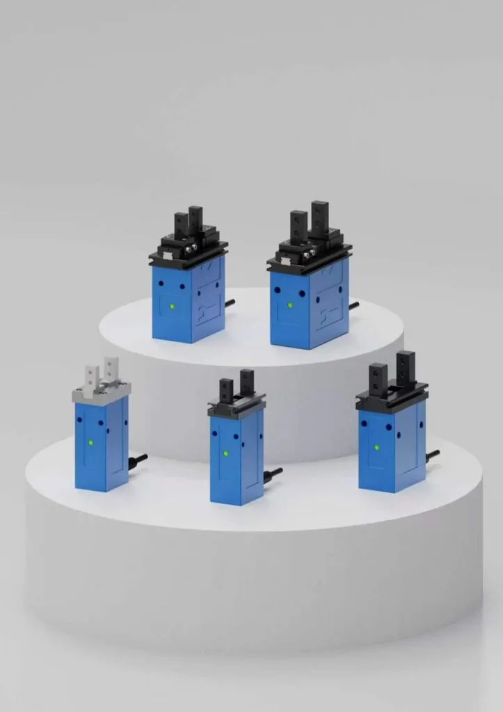
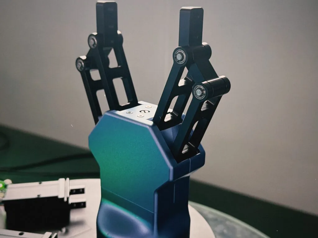
Heavier parts usually lead to the EPGL long-stroke series (IP40). For coolant or chip environments, ask us to confirm suitability before selecting a configuration.